Category: Manual (page 1 of 2)

Parameter Relations

An important aspect of Archimatix is the ability to build relations between parameters. There are two ways to designate relations between parameters: 1 inter-nodal connections, and 2. parameter expressions.

When one parameter is related to another, they can work together, i.e., when one parameter in the relation is modified, another  parameter will be modified as well based on a relation expression that determines the nature of the relationship.

For example, as a designer, you may want to designate the height of a building column to always be equal to the height of the ceiling beam. Once this relation is set up, then you can move beam up and down, and the column height will adjust itself to be identical to have height identical to the vertical displacement of the beam.

In the above GIF, we first translate the beam up and down, observing the height of the column to match it. Then with the beam still selected we modify its length, which is not related to any other parameters at the moment. Finally, we click on the column and adjust its height, observing that the beam is also being translated in the Y-direction to match.


Inter-nodal Parameter Relations

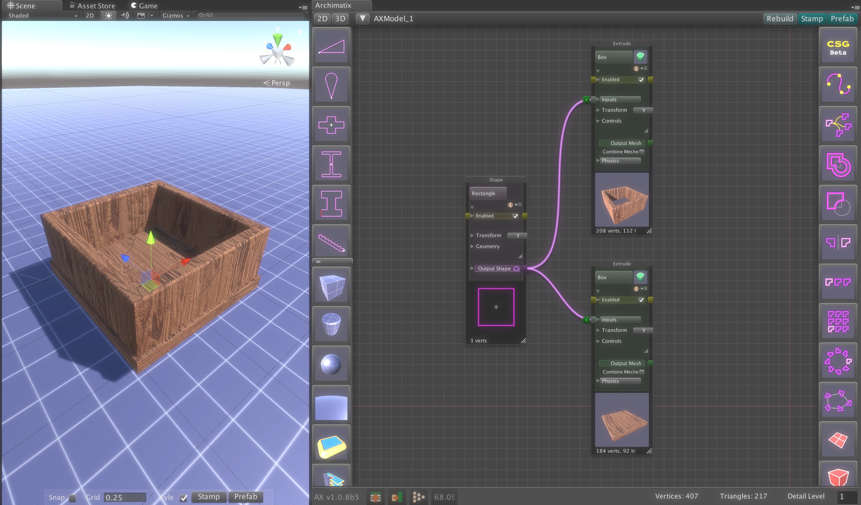
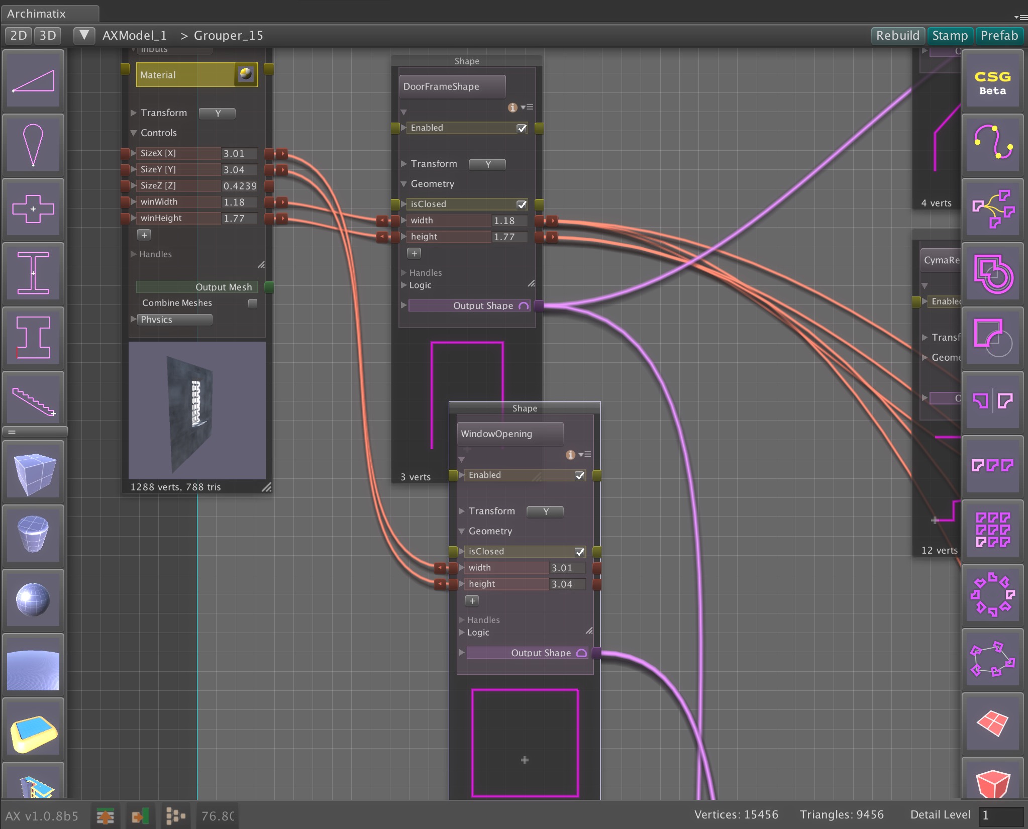
This is an inter-nodal parameter relation that connects the TransY parameter of the beam to with the height parameter of the column Extrude, as show in the figure below.

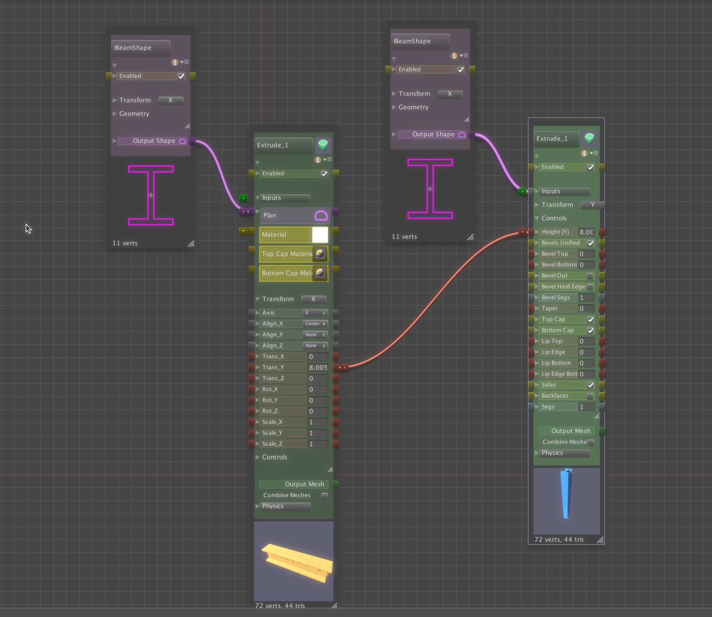
By simply connecting these two parameters we have related them as equivalent. But what if we want them to be proportional in some way rather than equivalent? For that, we would need to edit the default expressions for this relation.


Relation Expressions

The nature of the relation can be described with a mathematical expression. In the simple equivalent relation above, the default expression is not too intimidating mathematically. We can take a look at it by clicking on the red connection cable between the the two parameters.

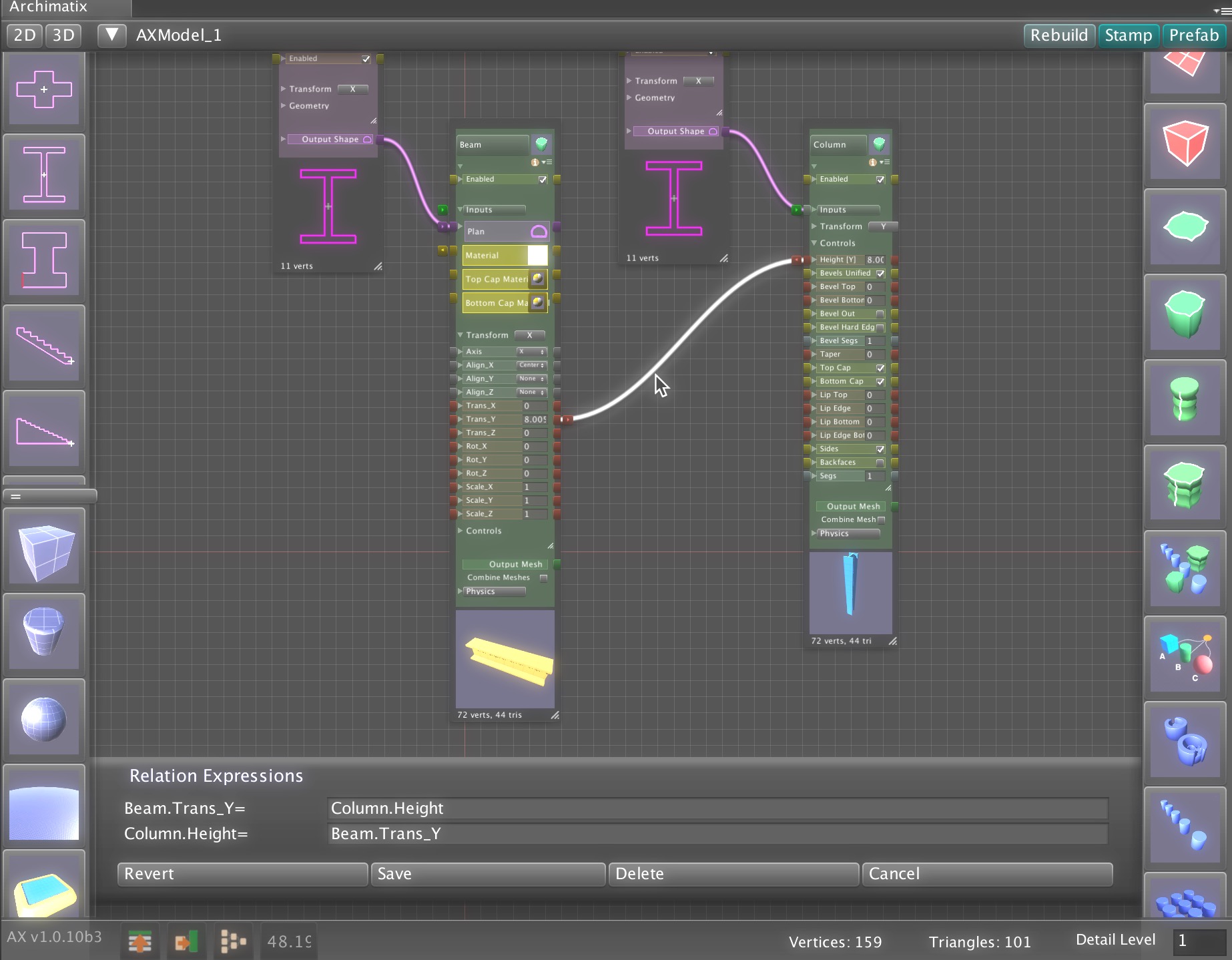
While the connection is selected, an expression editing box appears at the bottom of the node graph window. As we can see, the parameters are simply equal. We can modify these to something a little more complex.


Bi-direction Relations

Archimatix allows bi-directional flow in parameter relations. What facilitates this is that each inter-nodal relation provides for two expressions. The top expression, in the figure above, defines what happens to the Beam.Trans_Y when the Column.Height is modified. The bottom expression defines what happens to Column.Height when Beam.Trans_Y is modified.

While these expressions look identical, technically they are reciprocal. The key to bidirectionally is taking the time to author these dual expressions that are often, but not necessarily, reciprocal. The benefit to bi-directionality is that you don’t have to know which object is driving the other. You can simply click on any object of handle in the scene and start modifying, and the logic of the model will take care of everything. Most parametric systems do not feature this, leaving the user of the model to have to find out which object is the driver and which object is the slave.

If you do not want bidirectionally, you can always leave one of the expressions blank.

If we wanted a proportional relation here, we might edit these expressions to define that the beam should always be welded to  4/5 the height of the column.

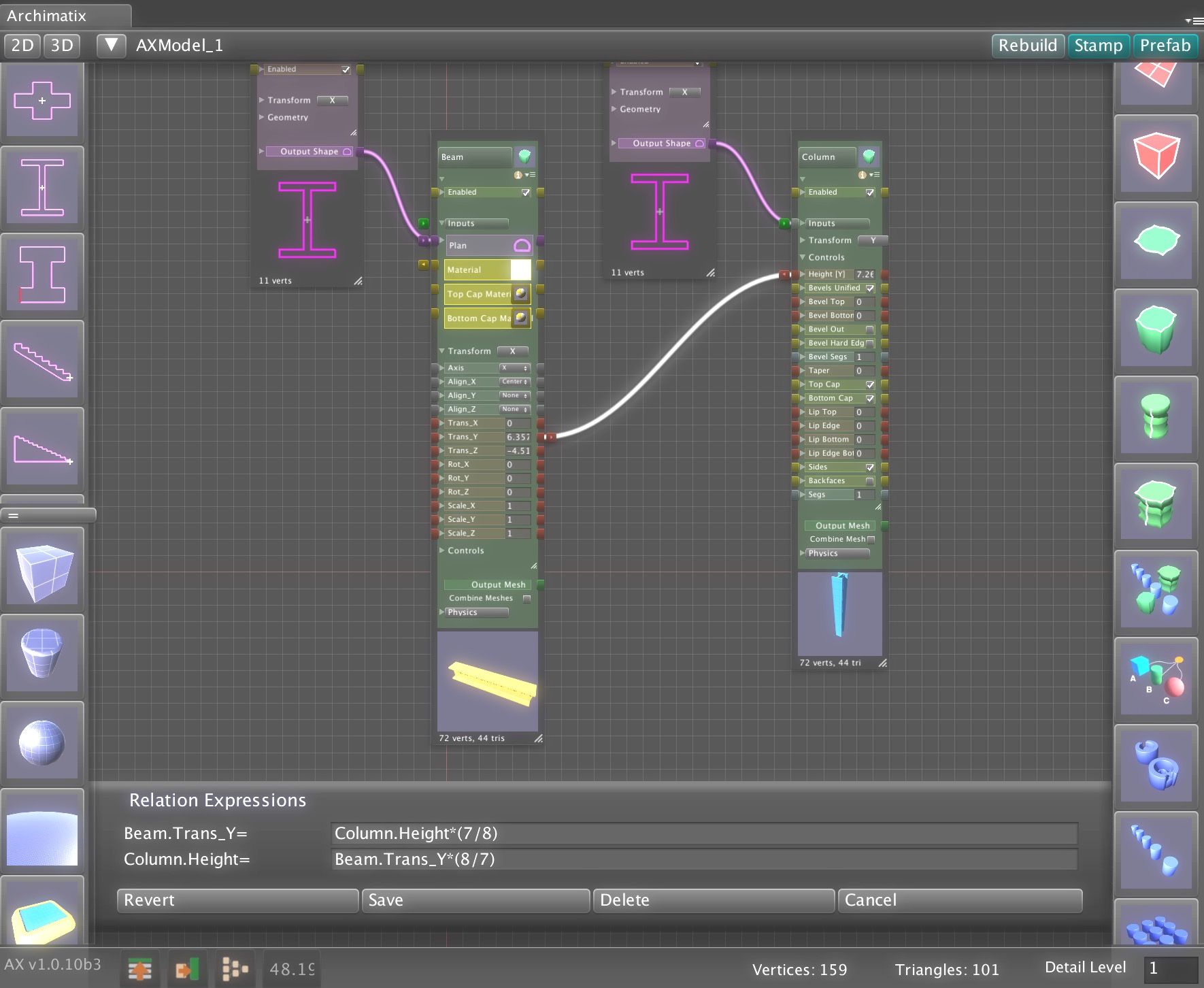
The expressions were edited to reflect this proportion mathematically and be reciprocal. Now dragging on either the column’s height handle or the beams translate Y will have the same effect.

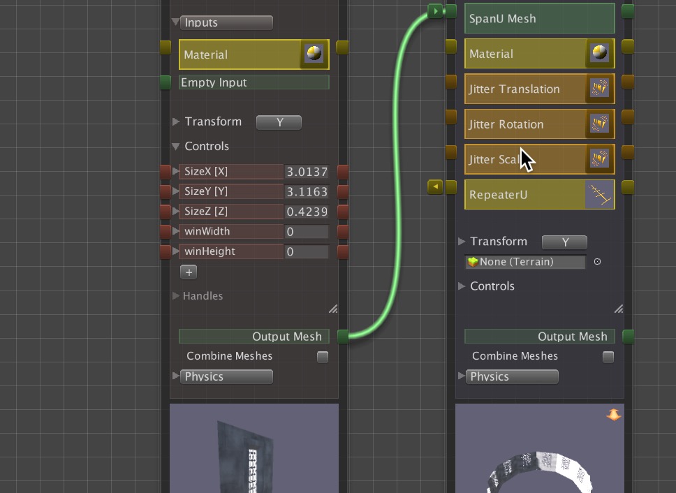
But what if we want the portion ratio of 7/8 to be a parameter? Currently, an inter-nodal expression only supports using the parameters on either side of the connector. In order to include multiple parameters in an equation, you can use parameter expressions.

Parameter Expressions

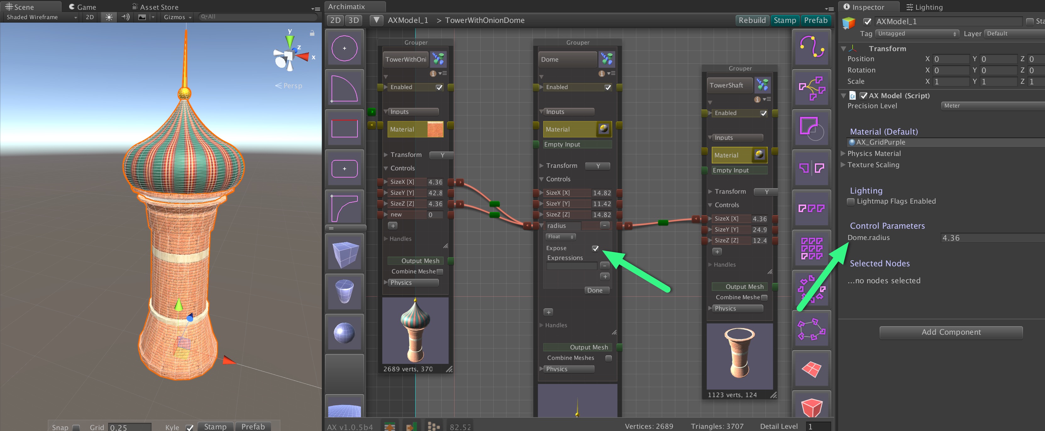
One or more parameter expressions can be attached to any parameter. These expressions are executed whenever that parameter is changed.

Grouper: Mesh Combination versus Encapsulation

As you add nodes to your model, your node graphs gets larger. The Grouper node helps you organize your graph and increase modularity for reusability of components.

There are two ways to use Grouper to organize you nodes: 1. Combination and 2. Encapsulation..

Simple Mesh Combination

Perhaps the simplest way to group nodes is to feed there out put into a Grouper’s mesh inputs. For simple graphs, this is a fast and easy way to work with multiple objects as one pieces.

For example, if we make a box with two Extrudes that share the same Rectangle Shape from the Library, we can easily manipulate both the base of the box and the sides by modifying the height and width of the Rectangle.

But what if we now want to repeat this box in a line? We have two separate meshes that make up the box. Before repeating lets combine these meshes with the Grouper Inputs.

Make sure that none of the nodes are currently selected (click anywhere on the node graph background) and then select a Grouper node from the righthand sidebar in the Node Graph Editor and connect the output of the two extrudes to the Grouper.

Now the Grouper Output Mesh can be fed into any other node as a single unit.

For example, click on the Grouper Output and then click on LinearRepeater in the righthand sidebar.

Now the combined meshes are repeated as a unity. If you stamp out the model, the bottom and sides are still separate GameObjects. If you would like to truly combine the meshes (perhaps to reduce draw calls or have them function as a unity as rigidbodies, you can click the Combine Meshes option under the Grouper Output.

The benefits of this form of Grouping is that it is fast and you can see all the nodes at once. However, as your graph gets more complex, seeing all the nodes at once can be too messy. Also, this method does not allow for true encapsulation of logical parts that can improve reusability of subsystems in other models. The next use of Grouper is improves these factors.


Mesh Encapsulation

You can also encapsulate nodes inside the Grouper by dragging them over the Grouper’s thumbnail. Nodes inside the Grouper form a subgraph that can be reused in multiple models.

In this example, we have a section of wall with a window. The main control is the Rectangle of the window opening.


The graph that powers this is looking a little complicated. In this case it would be getting cumbersome to connect all these mesh output to the inputs of the Grouper.

If we drag all the nodes over its thumbnail, then  we have created a subgraph that encapsulates all the nodes. Now we have a single node that hides all of its complexity.

By double-clicking the Grouper thumbnail, we can go inside the Grouper and continue to operate on its parameters, and relations.

To step back out of the Grouper, we can double click its thumbnail again or click else where in the “breadcrumb trail” at the top of the node graph window.

As with the Mesh Combination method, we now have a single mesh output that we can feed into other nodes, such as a RadialRepeater.


To adjust parameters of nodes inside the Grouper, we can open it, but that would break the concept of encapsulation we are trying to achieve. What would be better is to create proxy parameters in the Controls of the Grouper to define its parametric behavior. This essentially creates an interface to the subgraph so that we need not ever go down into the subgraph and be distracted by its details.

In this case, the interface might be the width and height of the wall and the width and height of the window opening.

For the opening, lets create window width and height parameters.


For the wall lets use the default SizeX and SizeY of the Grouper.

Lets open the Grouper (perhaps one last time!) to connect theses parameters:


Now that we have encapsulated the wall section model and provided an interface, we have hidden the complexity of the subgraph to allow us to think at a higher level as we continue to use this parametric wall section in other larger assemblies.

If you do find yourself going back into the Grouper to adjust parameters, then it may be a good idea to make proxy parameters in the Grouper for them. In other words, once you finish rigging up a subnode graph in a Grouper, you should never need to open it again.

Also, keep in mind that you can have Groupers inside Groupers, to further organize and encapsulate.


Also note, that a Material given to a Grouper will be inherited by its Groupers in the subnode graph unless overridden inside.


Models Output from Archimatix

If you would like to bring the fruits of your Archimatix (AX) labor to external applications such as Substance Painter or Quixel, you can export your models as OBJ or FBX. It is easy to export models from archimatix as OBJ or FBX using any of the free or paid assets in the Asset Store, once you Stamp your model out.


Stamping

When you Stamp your Archimatix model, you are creating a clone of the standard Unity GameObject hierarchy that AX and stripping it of any AX metadata. This leaves a GameObject hierarchy that is essentially “frozen,” i.i, no longer parametric.

To Stamp a model, be sure that it is selected in the Hierarchy window and then click at bottom of the Stamp button in the Scene View or the the upper right of the Archimatix  Node Graph Editor window.

At this point, the Stamped model no  longer needs Archimatix to be in the scene. It is also ready tobe further modified  by other assets in the Asset Store, such as ProBuilder for polygonal modeling or Surforge for PBR texture painting.

Prefabbing

The only way to create a Unity Prefab from an Archimatix model is to make sure the model  is selected in the Hierarchy window and then click the Prefab button at the upper right of the  Node Graph Editor window. This is similar to Stamping in that it “freezes” the model, but it also saves all of the meshes in the GameObjects to the AssetDatabase in an optimized way.

Note that you can not simply drag a Stamped model to the Project window to create a Prefab, since the meshes will not be in the AssetDatabase.

Exporting

Archimatix does not have a buit-in exporter yet, but once an Archimatix model as been Stamped or Prefabbed, you will find several free or paid assets for exporting models from Unity as OBJ or FBX.  For example, Scene OBJ Exporter.

Archimatix Runtime For Artists

If you’re artist who is not that into coding (just yet!), but you still want to create Archimatix Pro (AX) runtime behaviors, well, you can in version 1.0.6 and later!

While Archimatix parameters can be exposed to the interface of your model, allowing easy access to them via custom game scripts, you may also use  Unity’s built-in UI system or assets like PlayMaker to control the values of AX parameters with the help of an easy to create runtime controller.

Let’s jump right into a short example to show rather than tell! While you can control any manner of complex and sublime models you have created in AX using runtime parameters, in this example, we will keep it simple and just adjust the height of a Box at runtime using a UI Slider. For this example, we won’t eve use the Node Graph Editor.


Step 1. From the Unity menus, create an Archimatix Box.


Step 2. Select the Box in the Scene.

Step 3. In the Inspector choose to expose the Height parameter as a runtime parameter by clicking the checkbox to the left of the parameter name.

Step 4. Note that the Height parameter has appeared in the list of the model’s runtime parameters.

The exposed runtime variables are easy to use in any game script, but they can also be easily made  available for binding to Unity’s UI system, PlayMaker, or any other system that connects to dynamic variables. All we have to do is create an AXRuntimeController asset. Fortunately, this is done with the click of a button!


Step 5. Make sure the AXModel GameObject is selected.

Step 6. Click on the “Create Runtime Controller” button.

Step 7. Save the new controller file anywhere  in your Asset folder.


You’ve done it!

You now have an Asset that connects to Archimatix’s runtime parameters and serves as a source for for Unity’s UI system, PlayMaker, etc. When choosing a connection, use the runtimeController asset you just created as your source of variables.

You may not have realized it, but by clicking that button, you 1. created a GameObject in the AXModel hierarchy and 2. added a new component to it, the runtimeController asset you created.

If you select other parameters in your AX model to become exposed as runtime parameters, just click the “Create Runtime Controller” button again. This time it will not ask you to locate the file, but just overwrite the one you have already created.


Now let’s take a look at how we can connect your new controller to Unity’s UI.

Step 8. Create a UI Slider. Adjust its Max Value to 10.


Step 9. Add an Action to the Slider.


Step 10. Unfold the Box model, click on the Slider in the Hierarchy and drag the runtimeController to the ObjectField in the Slider Inspector.


Step 11.  For the Function pulldown in the Slider Inspector, choose your controller and the Box_Height variable.


By Jove! You’ve done it again!

You have just empowered your game interface to do runtime modeling! Check it out!


Step 12. Check your UI to make sure the Slider is visible in the Game View. Click Play and manipulate the Slider. The Box height should be adjusting as you move the Slider.


Colliders


Archimatix lets you specify the type of Collider you would like on the GameObjects that it generates. All of the Unity Colliders are supported. In order to have a collider automatically enclose a series of meshes, in the node palette you can specify that all of the individual meshes being output are combined.


Archimatix also lets you use meshes as colliders only, by letting you specify that the mesh should not have a Renderer attached.

Runtime Archimatix

Runtime Archimatix is available in version 1.0.5 -full documentation  coming soon!

With Runtime Archimatix available only in Archimatix Pro, you can create in-game interactive modelers of your own design. A good example is the Spaceship Shop demo scene included in Archimatix Pro. In this demo, you can use the in-game UI to deliver simple modeling functionality, such as changing the shape of the hull with runtime handles, choosing the engine type and size, as well as sizing and positioning the weapons. Such a shop could be part of a game or its own independent application.

Other examples might include in-game house construction, maze design and, well, anything you can dream up! By creating such runtime applications, you not only make environment and prop building simple, fun and thematic, but also generate opportunities for in-app purchases that go beyond the acquisition of modular inventory items.

In its first iteration, runtime Archimatix (AX) allows you to control AX parameters from your runtime scripts. This means that you can connect your  runtime UI to an AX model and control it in a way that works with your game design. For example, if your player can spend game dollars to build a house, then they can size the house interactively while watching the cost of the house vary with the floor area of the building.

To facilitate this, AX has an “Expose” checkbox under each parameter in the node palette. Once you check that, the parameter will be displayed in the Inspector for the AXModel. With the variable exposed at the model level, your script can easily access the variable to get and set its value.

In order to modify these parameters in runtime, you need a reference to the AXModel (a Component of a GameObject in your scene). In your MonoBehavior, add a public member of type AXModel:

using AX;

public class GrayShipDesigner : MonoBehaviour {

    public AXModel model;

}

After doing this, you can drag the AXModel aGameObject into the ObjectField in your runtime script. With this reference to the parametric model, you can get and set the parameters that you have promoted put to the model interface. When you set these parameters, they will ripple their value change throughout the graph based on the Relations you have established between parameters.

To make your code more readable, it may be good to set up references to the parameters so they are easier to get to:

using AX;

public class GrayShipDesigner : MonoBehaviour {

    public AXModel model;

    public AXParameter P_Radius;
    public AXParameter P_Channel;

}

In the Start function, you can establish these parameter references using the getParameter function. This function uses the name you have given the parameter in the graph to find the parameter:

 // Use this for initialization
 void Start () {

    // Establish refernces to AXModel parameters.

    if (model != null)
    {
        P_Channel = model.getParameter("Engine.Channel");
        P_Radius  = model.getParameter("Engine.radius");
    }
}


To modify the parameters you have a reference to, use AXParameter.intiateRipple_setFloatValueFromGUIChange(floats value) and then let the model know you are ready to have the changes regenerate the model while dragging with model.isAltered() or after UI edits are complete with model.autobuild().

 // Example of a UI callback function. This could be a delegate of a Slider that controls the radius. 

 public void radiusSliderUpdate(float val)
 {
    // Set the value of the parameter and let this change ripple through the network of Relations

    P_Radius.initiatePARAMETER_Ripple_setFloatValueFromGUIChange(val);


    // Let the model know that you are done making your changes,
    // but not necessarily to create new game objects.
    // isAltered() is often called during a repetitive change such as with a slider.

    model.isAltered();

     // Other relevant game state changes not necessarily related to Archimatix 
     
     radius = val;
     recalculate();
 }

   
 public void engineTypeDropdownUpdate()
 {
     // Set the value of the parameter and let this change ripple through the network of Relations

    P_Channel.initiatePARAMETER_Ripple_setFloatValueFromGUIChange(engineTypeDropdown.value);


    // Tell the model to rebuild its GameObjects. 
    // autobuild() is often called after a Dropdown or Checkbox UI is modified.
    
    model.autobuild();

    // Other relevant game state changes not necessarily related to Archimatix

    recalculate();
 }

That’s all that you need to get started with runtime Archimatix! There will be full API published eventually as well as some example scenes.

Detail Level

Since Archimatix is a non-destructive modeler that gives you great control over detail level, you can iteratively reach the optimal triangle efficiency versus aesthetic richness you would like for your model by simply dragging local parameters in the nodes or the global Detail Level slider.

Triangle density tends to be a product of 2D Shape segmentation.  You can set the segmentation of Plan and Section shapes to control the number of triangles in the meshes generated by the shapes. As you model, if you think certain forms look too faceted, you can go to their generating shapes and up the segs parameter.

Alternatively, you can use the Detail Level parameter at the lower right hand corner of the Node Graph Editor to decimate segs variables where ever they are found in the graph.

You can also use this detail control to create LOD version of the model. Eventually Archimatix will have an LODGroup creator.


Creating Custom Nodes

A great way to extend Archimatix is to create your own node to work with other nodes in the graph. While you can create your own node by saving  a graph you create to the Library or by creating a custom parametric Shape using AX Turtle scripting, you have the most power and flexibility to change the course of AX history by coding a node in c#.

Fortunately, its not that hard to create a node. All you have to do is derive a class from one of AX’s Generator classes. Most commonly, you will subclass Generator2D or Generator3D. You only need to override a couple of functions and, voila, you have created a custom node.

Location, Location, Location

Your script file and icon file can be anywhere in the project’s Asset folder your new node will be discoverable by AX. The only requirement for discoverability of your class is that, in addition to subclassing a Generator, you need to implement the interface ICustomNode. AX uses this Interface to search for custom node classes.

While your node icon can be anywhere in the Asset folder, it will be discoverable only if you name the icon image file according to the convention zz_AXNode-MyNodeName.jpg and place it anywhere in the Asset folder, your node will appear in the right sidebar menu of the node graph window, toward the bottom of the menu.

Making your Node Iconic

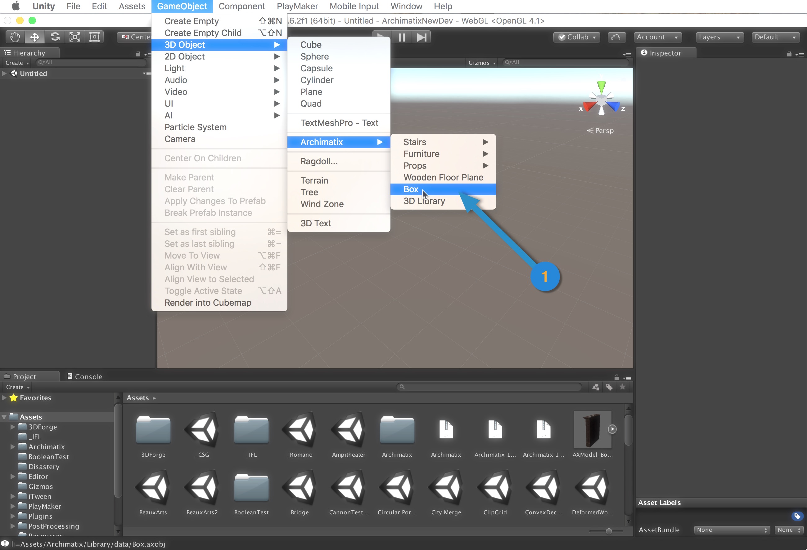
If you don’t create your own node icon image, one will be automatically displayed for you in the right sidebar of the node graph. AS a generic icon, the only way a user will know that it creates an instance of your node is by the tool tip that appears when you mouse over it. For this reason, it is probably best to create your own distinctive look!

Your node icon image should be square and saved as a jpg file. If you have named your image file according to the convention above, then it will be displayed in the sidebar at 64×64 pixels so your original image file should be that size or larger. In order to work contextually with the other nodes in the sidebar color-wise, you can use the blank image icon to the right as a background. Once your image is saved, select it in your Unity Project window and, in the Inspector, set the Texture Type to Editor GUI.

Its All What You Node

A custom node written in C# is really just a subclass of a AX.Generator. A Generator has inputs, parameters, generative logic and outputs. The inputs may be Shapes, Meshes, Prefabs, or the output of any AX node. You can determine what output parameters you would like to provide for.

A Generator gives a node a behavior. The actual node class itself  is AXParametricObject, which subclasses AXNode. Before going too deeply into the structure of AX, lets look at an example of what a Generator subclass might look like.

To get started, duplicate Archimatix/Scripts/Core/Generators/CustomNodeTemplate.cs. Change the node name, and edit the generate function and you have your own node!

Custom Zones in the Node Palette

In addition to SceneView Handles, you can also create custom GUI to insert into the node palette. There are four zones in the node palette which are controlled by GeneratorHandler functions you can override. The four zones are depicted in the following diagram.

To add GUI elements to your custom node palette, override one of these four functions. The current y-value for the GUI zone is passed into the function. You must keep adding to this cur_y and return the final value for cur_y at the end of the function.

The function may initialize variables to help with layout of the EditorGUI elements.

public override int customNodeGUIZone_1(int cur_y, AXNodeGraphEditorWindow editor, AXParametricObject po)
 {
     int     gap         = ArchimatixUtils.gap;
     int     lineHgt     = ArchimatixUtils.lineHgt;
     float     winMargin     = ArchimatixUtils.indent;
     float     innerWidth     = po.rect.width - 2*winMargin;
 
     Rect pRect = new Rect(winMargin, cur_y, innerWidth, lineHgt);
 
     // Create GUI here
 
 
     return cur_y;
 }


Texture Mapping

Textures are often thought of in two ways. Either tiled textures that can repeat indefinitely with no apparent seams or texture atlases, where a region in the texture image is exclusive to a polygon in the mesh.

2D Library

We can consider Shapes to be “closed’ or “open.” Of course, any open shape can be closed and any closed shape set to open, but some shapes lend themselves to one or the other. For example, a gear shape, would normally be closed while a molding profile would normally be open.

Closed Shapes


Primitives


Plans


Sections


Open Shapes

Column Profiles the are Lathed


Wall Sections the are PlanSwept


Moldings that are PlanSwept


Older posts

© 2024

Theme by Anders NorenUp ↑