After many requests to port Archimatix to Unreal Engine, we are finally going ahead with the project!
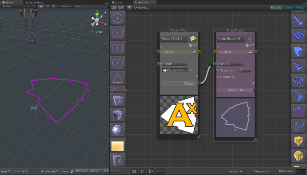
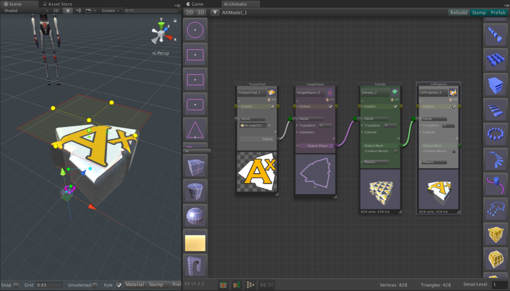
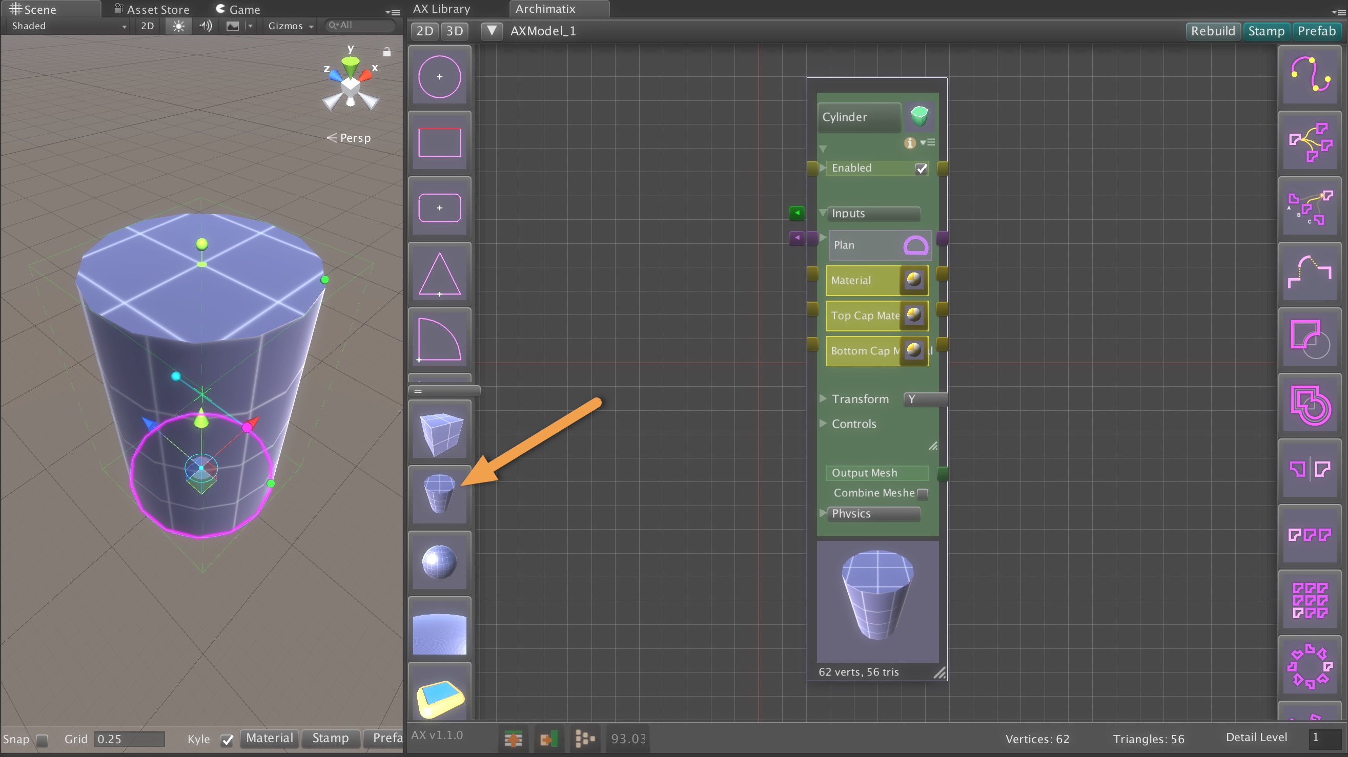
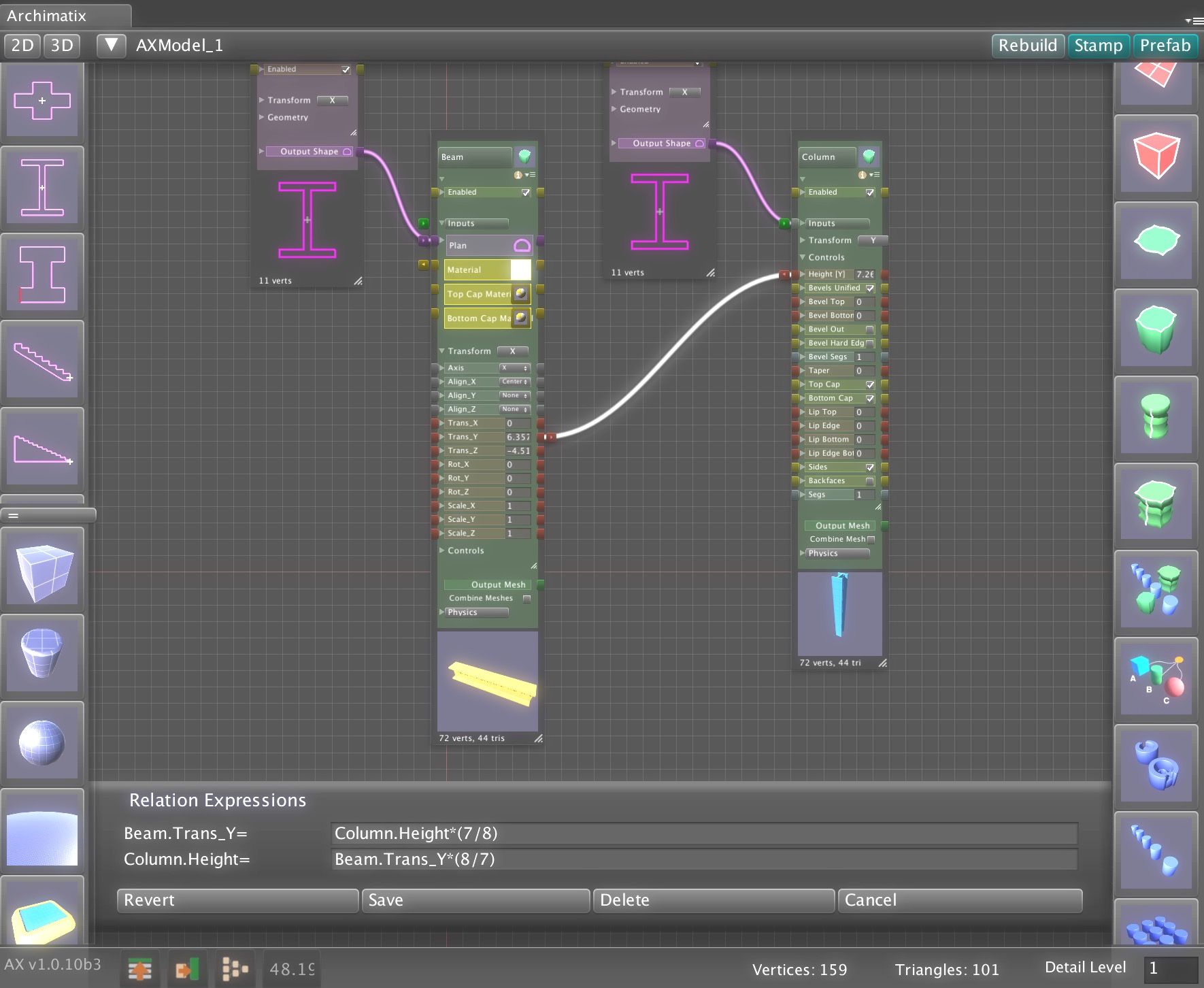
Unreal Engine already offers a powerful suite of tools for procedural modeling and content generation. By bringing Archimatix (AX) to Unreal, we aim to extend that toolkit with the architectural domain expertise and design workflows that AX has been refining for years. This port will leverage Unreal’s robust C++ and Blueprint libraries—along with its mature node-based editing environment—making development more streamlined than ever. In contrast to Unity, where we had to engineer our own graph editor due to the lack of a stable API, Unreal provides the foundation we need to deliver a richer, more integrated parametric modeling experience.
Community Impact
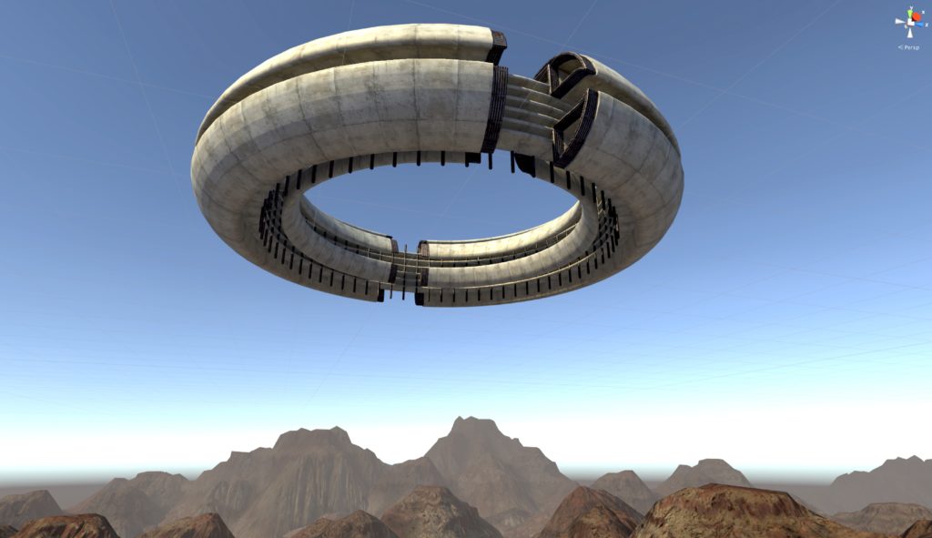
With AX in Unreal, creators across disciplines will be able to design complex, parametric structures directly inside their real-time projects. Game developers can rapidly prototype entire levels or generate unique architecture with a few tweaks to a node graph. Architects and visualization specialists can explore design variations interactively, presenting clients with living, explorable spaces rather than static renders. Educators and students gain an accessible gateway into parametric thinking, bridging the worlds of architecture, mathematics, and interactive media. By opening these workflows to the Unreal community, AX will help democratize procedural modeling and empower creators to build imaginative, dynamic worlds more efficiently than ever.
Goals
Port Core Functionality
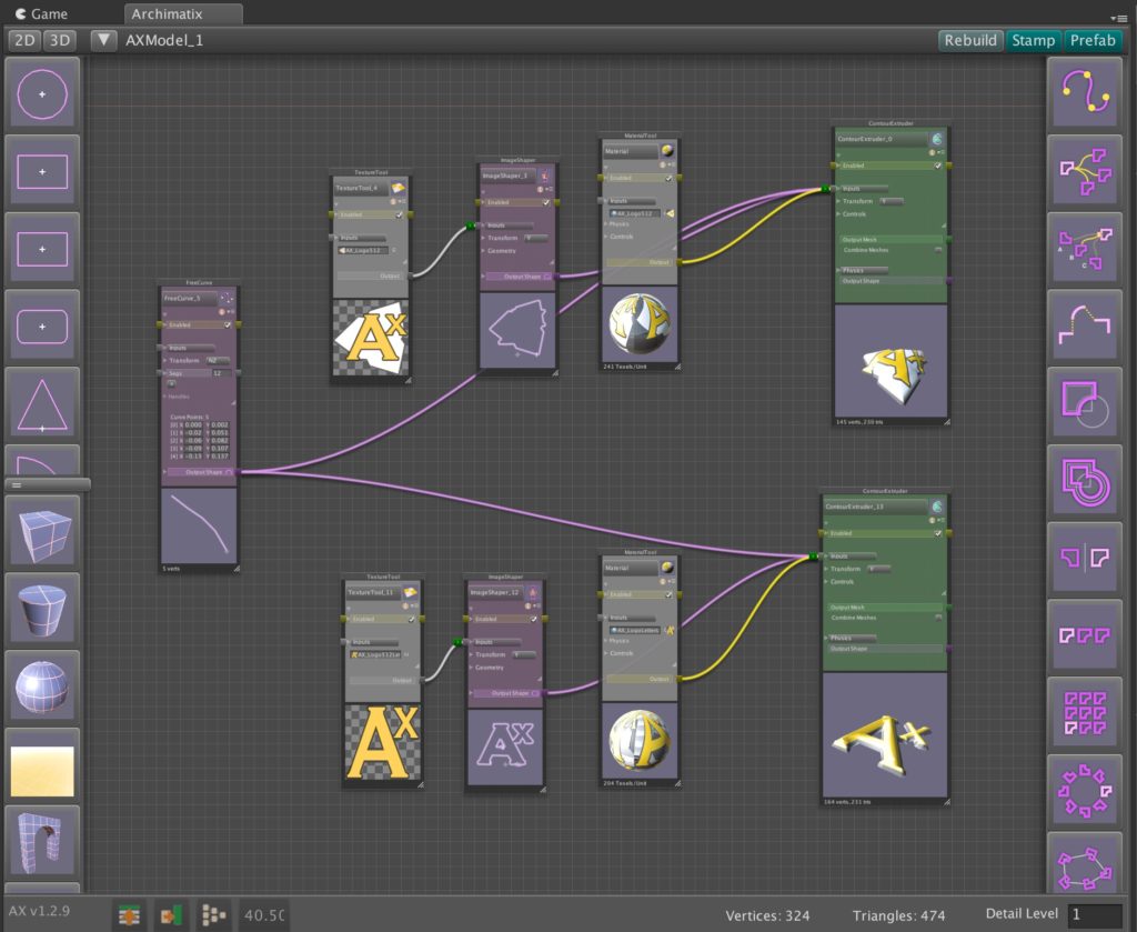
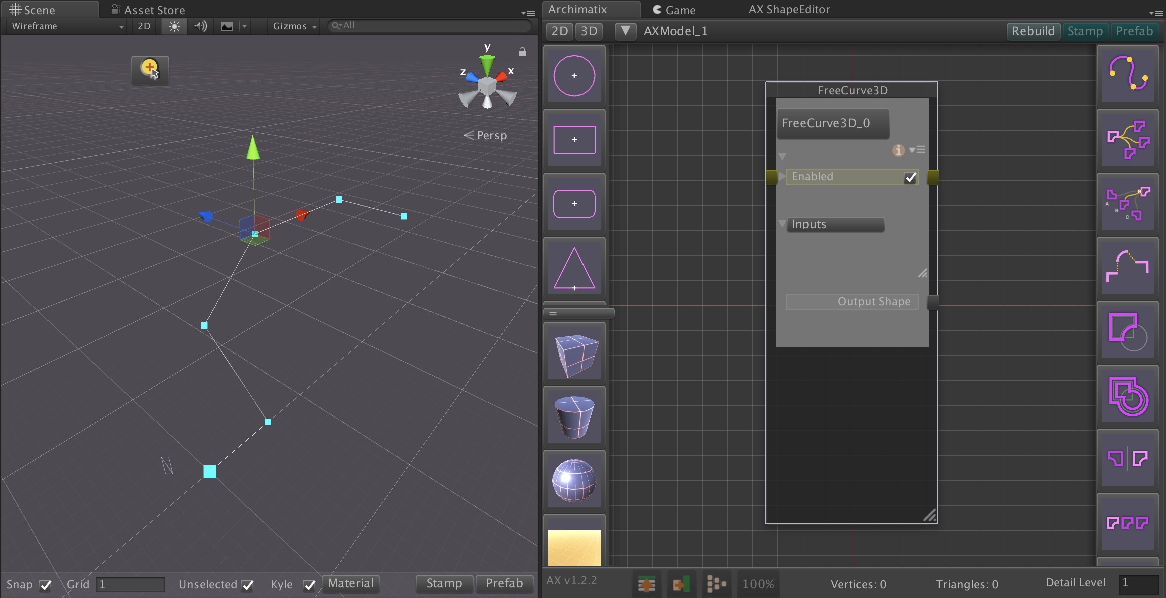
- Translate the unique nodes of Archimatix’s parametric graph system into Unreal’s C++/Blueprint environment.
- Ensure real-time parametric editing and procedural mesh generation are fully optimized for Unreal’s rendering and physics systems.
Integrate with Unreal Workflows
- Expose Archimatix graph nodes to Blueprints, enabling seamless integration into game logic and procedural level generation.
- Support Nanite meshes and Lumen lighting for next-gen performance and fidelity.
- Make assets fully compatible with Unreal’s Asset Browser and Sequencer for virtual production workflows.
Community & Marketplace Release
Provide sample projects showcasing use cases: level design, world-building, and real-time architectural visualization.
For our long-time Unity users, rest assured: this porting effort will not replace or diminish support for the Unity version of Archimatix. On the contrary, the work we’re doing to bring AX into Unreal will strengthen the entire project. Advancements in the core parametric engine, workflow refinements, and new node features developed during the port will flow back into the Unity edition. By expanding AX’s reach, we’re ensuring its continued growth, sustainability, and support across both engines—so whether you build in Unity or Unreal, you’ll benefit from the innovations ahead.


Recent Comments