Category: Uncategorized (page 1 of 2)

Getting Started with Archimatix2

Archimatix2 (AX2) is a node-based parametric modeler for Unity, rewritten from the ground up to emphasize C# scripting and runtime performance. Unlike Archimatix Pro (AX1), which focused on visual editing, AX2 is built as a developer-centric tool—lean, flexible, and optimized for integration into your game’s logic.

As a scripting API, AX2 may feel less intuitive at first, especially if you’re coming from the visual graph editor of AX1. It has a steeper learning curve, but it rewards that investment with greater control, automation potential, and runtime capabilities.

In this brief introduction, you’ll get oriented to the AX2 environment, learn how to script with its parametric nodes, and begin creating procedural models through code.

Whether you’re generating geometry at design time or dynamically at runtime, AX2 gives you the building blocks to think like an architect—and build like a coder.

And so it Begins!

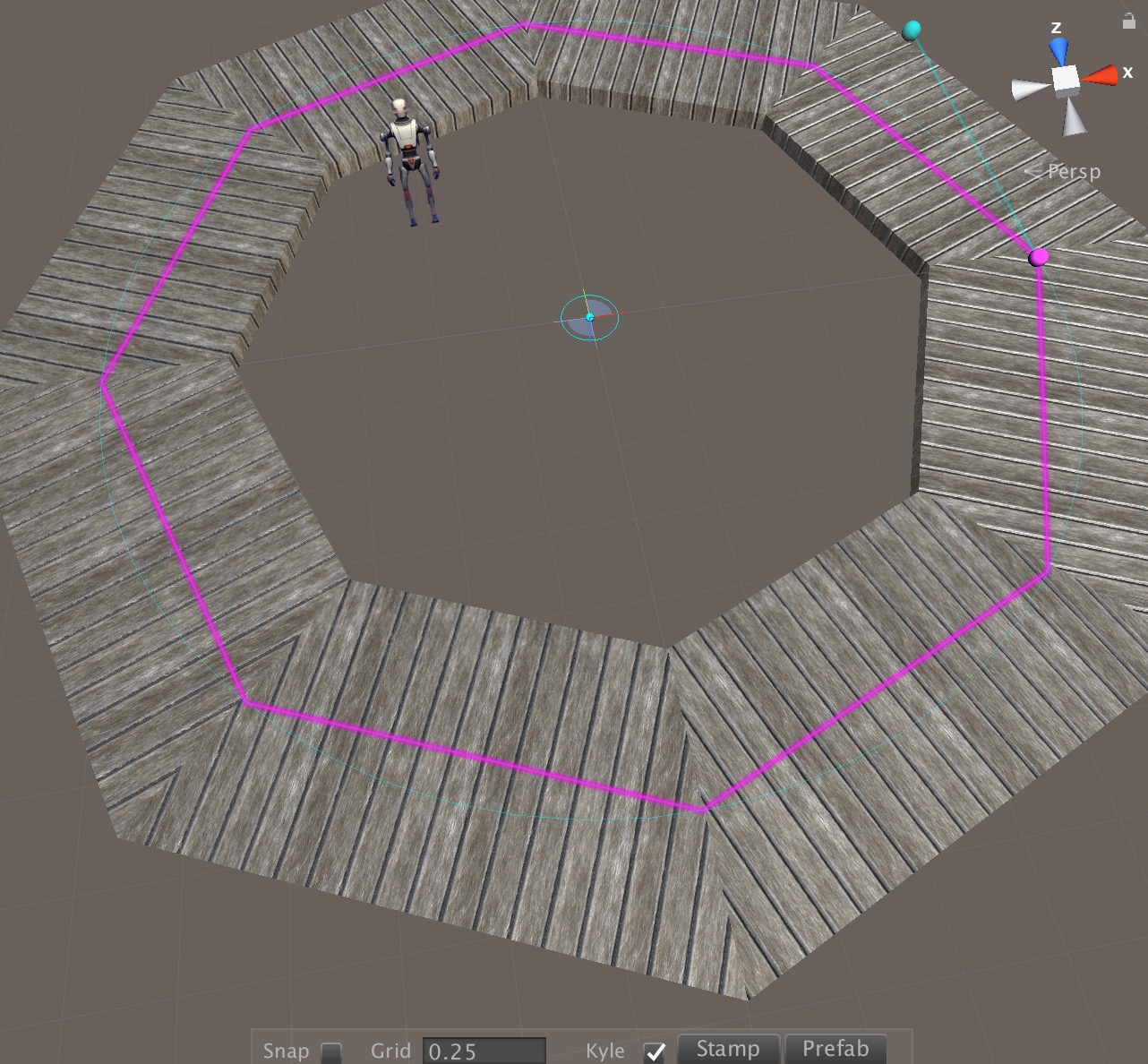
Let’s add your first AX2 parametric model to a new scene. In the top menu in Unity, choose “AX2/Add Model and Node.”

Choose “Stair” from the list that pops up…

You should now see your first AX2 model! There aren’t any editor handles yet, but you can adjust the Stair parameters using the Inspector.

Creating this Stair node is matter of writing a c# class that extends a base class called MultiBlockGenerator. To get a first look at what such a class looks like, open Stair.cs in an editor.

To the uninitiated, this class may look daunting, but everything outside the Generate() function is generated automatically by the NodeClassEditor, which we will discuss later. As the Node developer, your main task is to implement the Generate function.

/// <summary>
        /// The main function of a Generator.
        /// </summary>
		/// The Generate function: Creates one or more RenderBlockInstances.
        public override void Generate()
        {
            base.Generate();

            int stepCount = Mathf.CeilToInt(size.y / riser);

            float   actualRiser = size.y / (float)stepCount;
            int     subber      = topTread ? 0 : 1;
            float   treadX      = size.x /(float) (stepCount- subber);

            tread.size.x         = treadX;
            tread.size.y         = treadThickness;
            tread.size.z         = size.z + treadOverhang;
            tread.bevel         = bevel;
            tread.bevelSegs     = bevelSegs;

            tread.needsRigidbodies = needsRigidbodies;
           
            tread.Generate();

            Matrix4x4 worldM = WorldMatrix() * localMatrix; 

            int steps = topTread ? stepCount+1 : stepCount;
            for (int i=1; i< steps; i++)
            {
                Matrix4x4 m = Matrix4x4.Translate(new Vector3(treadX * i - treadX * .5f, actualRiser * i - treadThickness, 0));
                RBI rbi = tread.InstantiateProduct(m);
                renderBlockInstances.Add(rbi);
            }

            ApplyContextMatrix(contextMatrix * localMatrix);

        }

The first thing the code is doing is to set the size values for the Tread, which is really another Node called BeveledBox. By the time the Generate function is called, the local variables have the Parameter values already, so you can use tread.size.x and stepCount, etc. These Parameters were defined using the NodeClassEditor.

Once the Tread has been sized and it has been generated, then it can be instanced in a loop, with each instance being translated to its location in the Stair using Matrix operations.

In general, creating a new Node is a matter of defining the Node’s parameters using the NodeClassEditor and then crafting the implementation of the Generate function in c# – the AX2 system will take care the rest.

As an exercise, duplicate the Stair.cs file and call it SpiralStair (also, rename the class inside the new file). Already you should have a new node in the Node list when you choose AX2/Add ModelAndNode. Now edit the Generate function to rotate each step by some degrees. Don’t add any Parameters to your model just yet and instead hardcode a value for the Y-rotation. The rotation can be defined by adding a call to the Matrix4x4.Rotate command.

Good luck!

UVs and BreakAngles

The default UV logic you are seeing is the most architectural in the sense that typically floor materials like tiles or wood planks don’t really get narrower as the go toward the center of a circle. Instead, wooden planks would mitered. Such joints or architectural seams are often articulated with structural pieces like wooden framing pieces:

Archimatix Roadmap

V 1.0.7

Subdivision

Deformers

Adjustable max-min settings for Parameters


v 1.1.0

Shape Align

FreeCurve points to Parameters Binding

Node graph optimizations (hide relations cables, try bgtexture, etc.)

Lofter (ship hull’s, etc.)


V 1.2.0

3D Splines

3D Spline Sweep Mesh

3D Spline Repeater

Catmull control points

Road networks with intersections


V 1.3.0

Replication

Reduce Nodes to Thumbnails when zoomed out.


V 1.4.0

WinWall – 2.5D Booleans for cutting wall openings.


ArchSpandralShape

Test Video

TestjQuery

Hello

Introducing the Node Graph Editor


Basic Layout

Library Sidebar

Node Menu Sidebar

Node Canvas

Bottom Menubar


Basic Navigation

Click anywhere on the node canvas to pan it.

Use your scroll-wheel to zoom in and out, centered on your mouse cursor


Creating a 2D Node

Choose a Circle from the Library sidebar menu

Click on the node palette to move it.

Create a 3D Node

Click on the Output Parameter of the Circle Node (without dragging).

Move your mouse cursor to the righthand sidebar menu.

The sidebar menu has filtered the nodes so that only nodes that can receive the Circle Shape Output are displayed.

While hovering over the node sidebar menu, use your scroll wheel to scroll down to the Extrude node.

Click once on that node. The Extrude node should appear on the node canvas just to the right of the Circle.


Repositioning Nodes

Click on the node palette header bar or the thumbnail at the bottom of the palette and drag the node palette to a new position.

Move the Extrude palette to the left of the Circle palette, the connector between the two will wrap around to show that this is a directional relationship, i.e., the output of the Circle Shape “flows upstream” to the input of the Extrude node.


Adjusting the Node Thumbnail View

Mouse over the upper-righthand corner of the thumbnail at the bottom of the Extrude palette.

After a small orange sphere appears, click and drag the sphere to orbit the thumbnail view camera.

Dolly the thumbnail view in and out by holding down the ⌘ key (MacOS) or the control key (Windows) before clicking and dragging.

.

Transformation Parameters

Open the Transformations foldout in the Extrude’s node palette.

Click on the Trans_X parameter and slide to the left and right.

Control Parameters

Open the Controls parameters foldout on the Extrude node palette.

Click and drag the Extrude [Y] parameter. The hight of the extruded Cylinder will increase.


Node Stats

At the bottom of the Extrude node palette is a display showing the number of vertices and triangles in the output mesh.

Open the Geometry foldout on the Circle node palette.

Increase or decrease the number of segments using the segs parameter slider.

Notice the number of verts in the Circle stats display is updated, as is the mesh stats for the Extrude.

Bottom Menubar

Click the first button on the menubar at the bottom of the Node Graph Editor window. This will re-fold all the parameters foldouts that you have currently open.

Clicking on the next button, the “”Close All Tools” button, will hide any Material nodes, Tool nodes and Shape Nodes.

Clicking on the third button will show all nodes in the Graph.

Note the stats summary displayed on the right side of the bottom menubar. This is the count of vertices and triangles that your entire model will have when built.


Parametric Shapes

Parametric shapes are the heart of Archimatix modeling. Much of the form generation in real architecture is defined by shapes that are then extruded, swept and repeated. In this sense, architectural forms are a departure from sculptural forms such as organic bodies, automotive forms or geological formations which are more topological in nature and best model with 3D booleans and sculpting tools found in Maya and ZBrush. Much of architecture, on the other hand, can be described digitally using plan shapes and section shapes. In Archimatix, plans and sections are usually parametric shapes.

A parametric shape is a 2D form that is generated by a certain geometric logic and sized by input parameters. A simple but common example of a parametric shape is a circle, which is defined simply by a single parameter, the radius. The full description of a circle at runtime in Unity is a set of vertices that are in its circumference. Depending on the detail level, there may be dozens of vertices. But for the person using a circle for modeling, the radius parameter is a convenient way to think more abstractly about the shape.


More examples of parametric shapes, such as the ArchShape can be found in the Archimatix 2D Library. Many of the parametric shapes that ship with archimatix are listed in the sidebar to the right.

To create your own parametric shapes, you can start with an empty Shape node and code your own logic for the geometry using parameters you define yourself.


Getting a Handle on PlanSweep


Voila_Capture 2014-10-02_05-40-49_PM

Let’s take a look at how Handles can help you take control of Archimatix objects in the Unity SceneView. When you grab an object from the Archimatix library, it appears in the scene and is automatically selected, revealing the Handles that have been incorporated into it. By clicking and dragging these handles, you can alter various parameters. For example, with the conical object above made from a PlanSweep Generator, clicking on the centroid of the Section shape lets you change the size of the cone and the angle of its slope.

Voila_Capture 2014-10-02_05-41-16_PM

Advanced – Become a Handles Handler!

If you interested in making your own parametric objects, you can add Handles to customize how your users will interact with them. If you combine two shapes in a PlanSweep Generator, you will automatically have the Handles associated with the individual shapes. But you can go ahead and add your own handles as well. To do this, open the Handles section on any Palette and click the “+” button. Once the new Handle has been created, you can name it and then fill in the X, Y, and Z fields to tell the handle where it should place itself at any given time. In the fields add numbers or expressions using parameter names from the Controls section and mathematical symbols or functions.

For example, if you would like an outrigger handle that is always at twice the radius of an object, then you could fill the X-field in with 2*radius. As you slide the radius slider, on the palette, the handle in the SceneView will always be on the X-axis two radius’ away. Now, to have the handle alter a parameter, you add an expression (below the position fields).


Steampunk Made Easy!

While adding the new Combinator palette, I decided to go Steampunk with the help of some textures in the free set from Allegorithmic.

Steampunk1Steampunk 17

Older posts

© 2025

Theme by Anders NorenUp ↑