When a form is highly geometric, varying according to well-defined relationships, it often pays to take the time to codify that geometry and those relationships in a reusable parametric object. The effort taken in doing so may, at times, seem to be taking the long road to a solution, but it often pays off as you begin to use the “tool” you have created many times in multiple situations as you develop various environments.
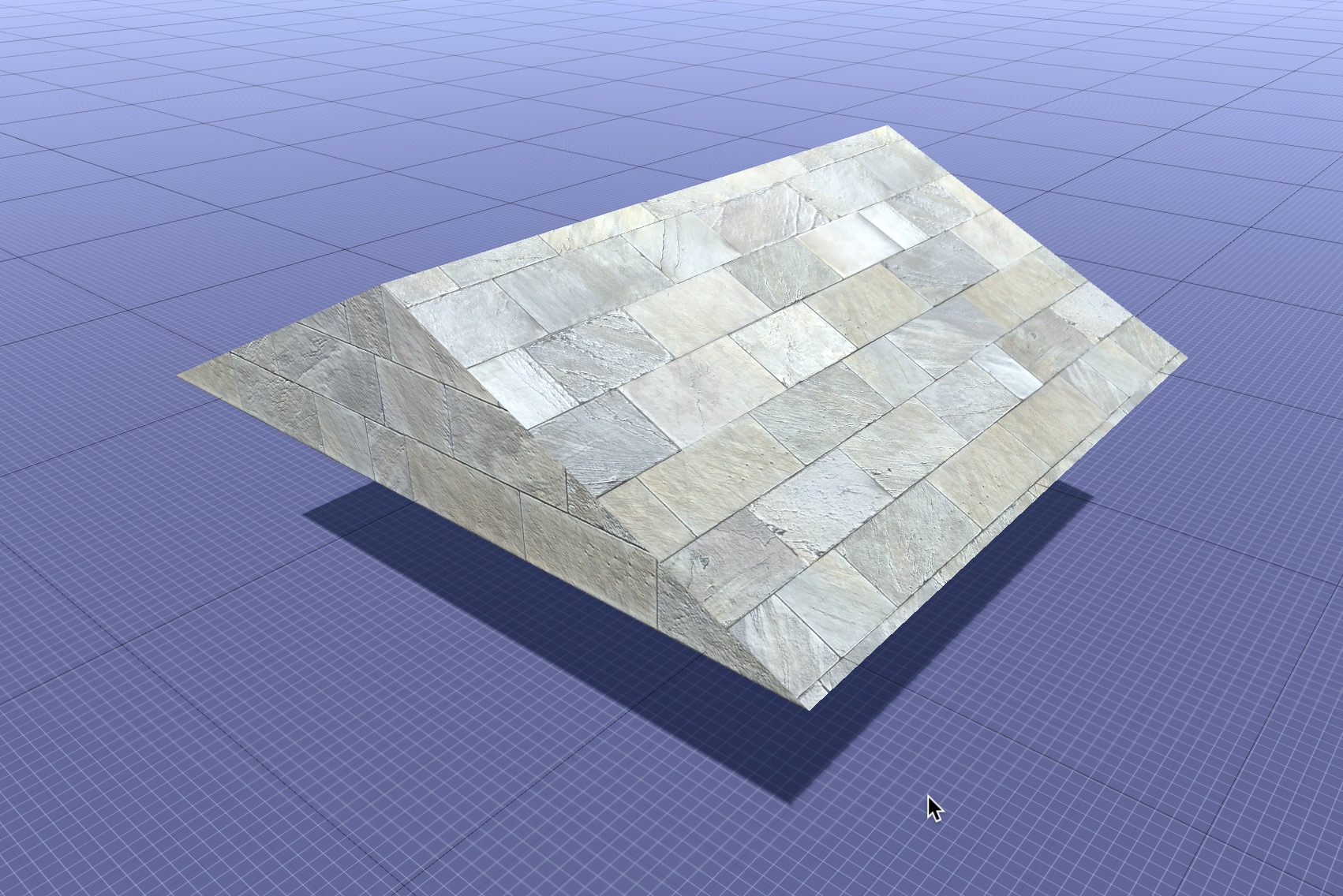
 The parametric form we will look at in this tutorial is a gabled roof, the mainstay of many types of vernacular and monumental architecture from Viking halls to Roman Temples.
The geometry of a gabled roof is simple, being based on an isosceles triangle, and will serve as an excellent example of how to describe interactive geometries of architectural forms for Archimatix.
Controlling Geometry
The key benefit of parametric modeling is to allow the end user of the model to vary the form of an object using relatively few controls. For example, a roof may have lots of detail and decorative features, but the main interactive handles are simply for width and height. For our gabled roof, we will consider the main controls to be the bounding box of the roof: SizeX, SizeY and SizeZ.
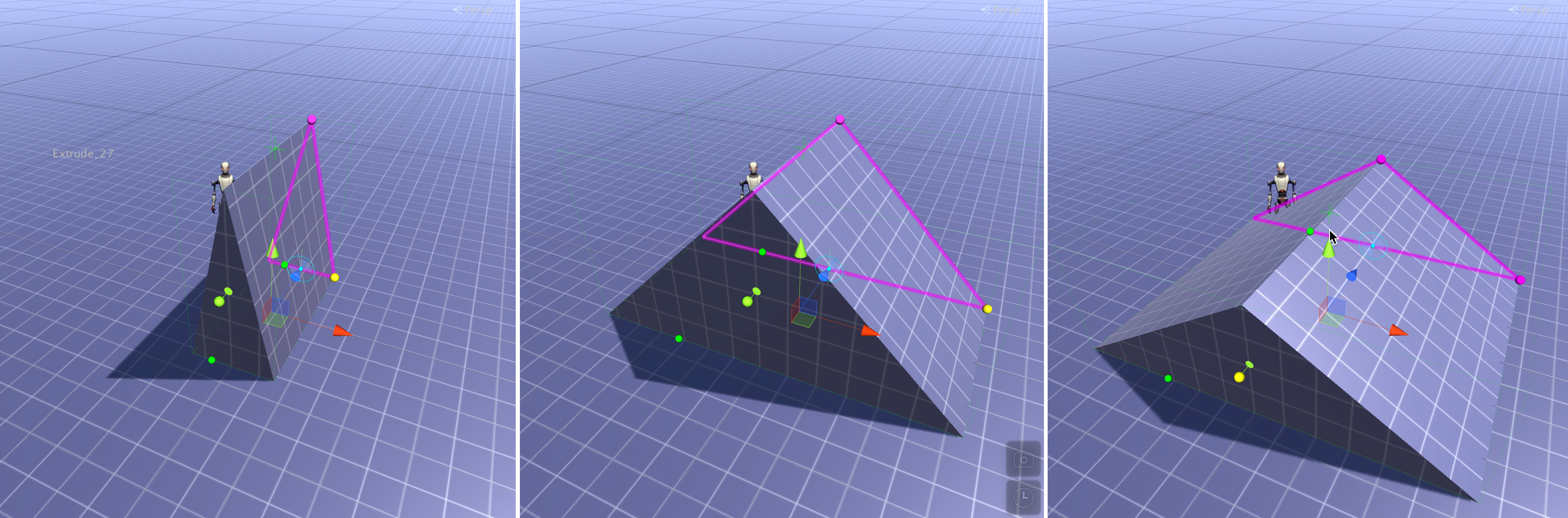
 In the GIF to the right, we see that Archimatix has added bounding box handles for us to manipulate in the Scene View. While we are thinking about the Sizes, the model is automatically taking care of the changing length of the wooden raking rafters based on the geometrical smarts we added to the model.
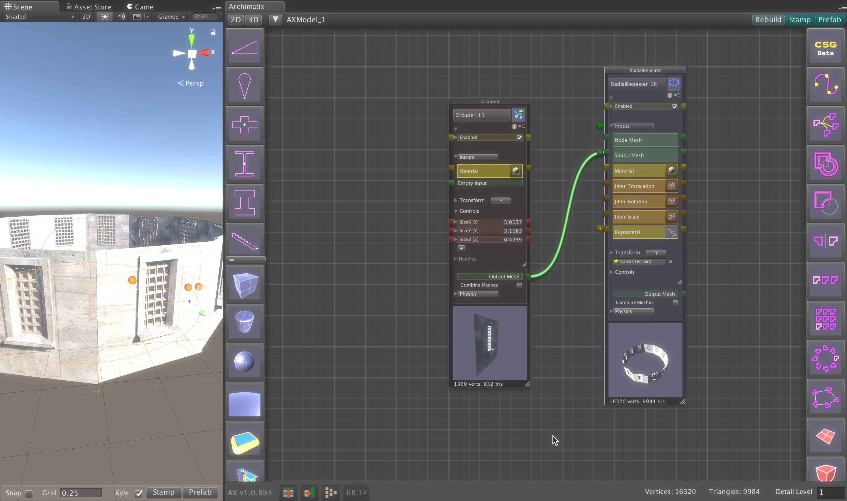
 The work we do to make a parametric object, such as a roof, pays off in spades as we feed the output of the object into other nodes, such as Deformers, as depicted in this GIF. As you layer modifications on top of your parametric object, a kind of magic sets in, where the user of your model experiences the joy of non-destructive editing.
A best practice in parametric design is to start with a diagram where you can draw a typical layout and add variables as dimension lines. For example, the gabled roof can be be represented as an isosceles triangle.
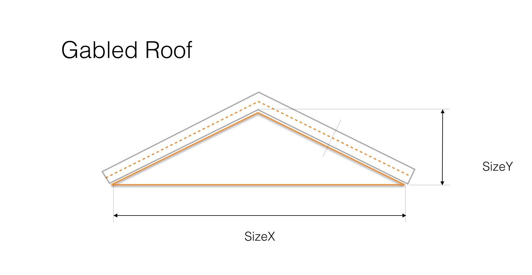
In this image, we see the dimensions SizeX and SizeY that will control our basic geometry. SizeZ is the depth of the roof (going into the page). In architectural parlance, this is called an elevation drawing.
We could simply instantiate an Isosceles Triangle from the 2D parametric library and use the ready-made handles, but since we are going to develop this model to be something more than an extruded triangle, it will pay to start with a Grouper node which will become the interface to our parametric gabled roof, relating the SizeX and SizeY of the Grouper to the Isosceles Triangle’s width and height.
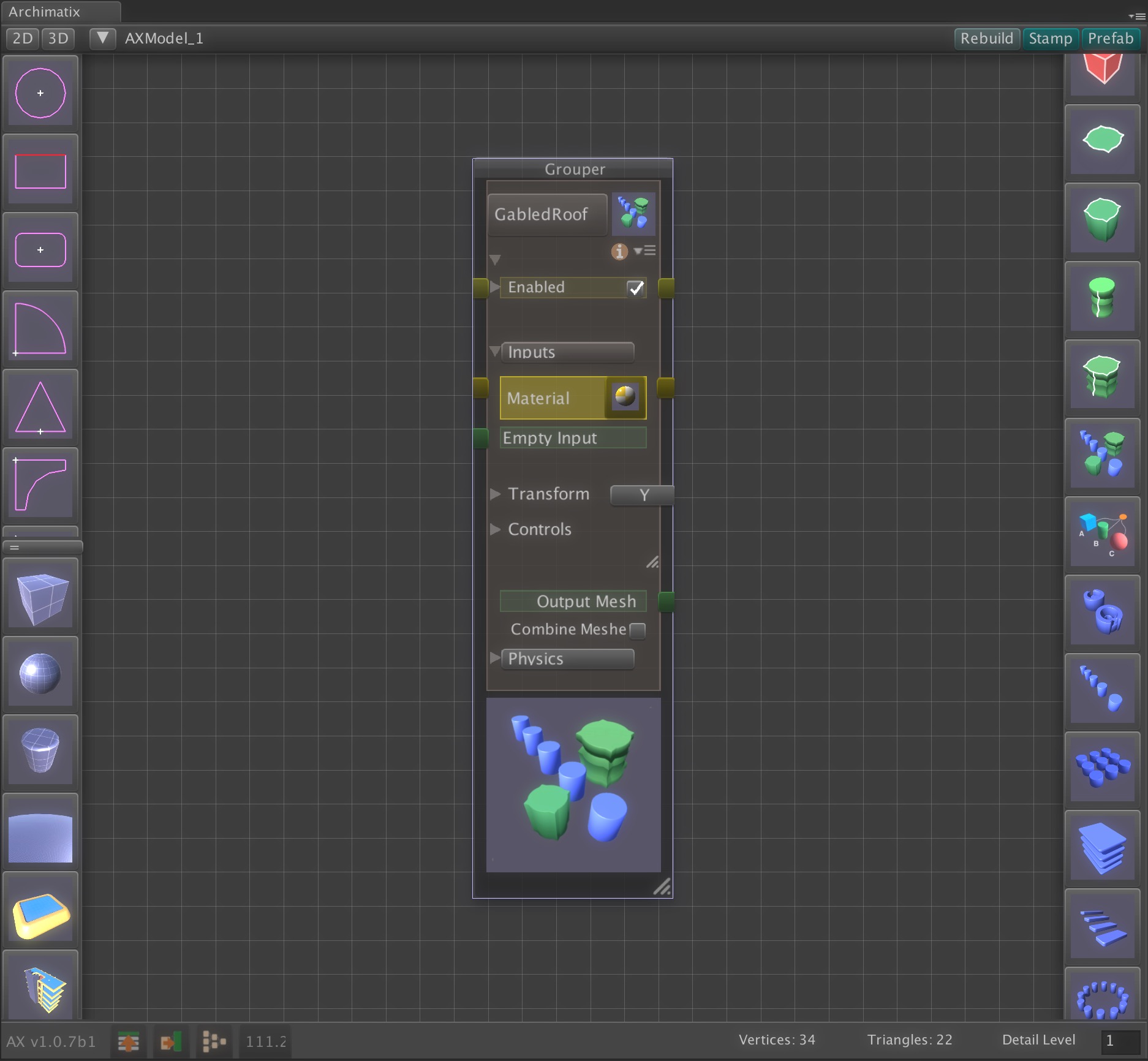
Step 1: Create a Grouper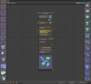
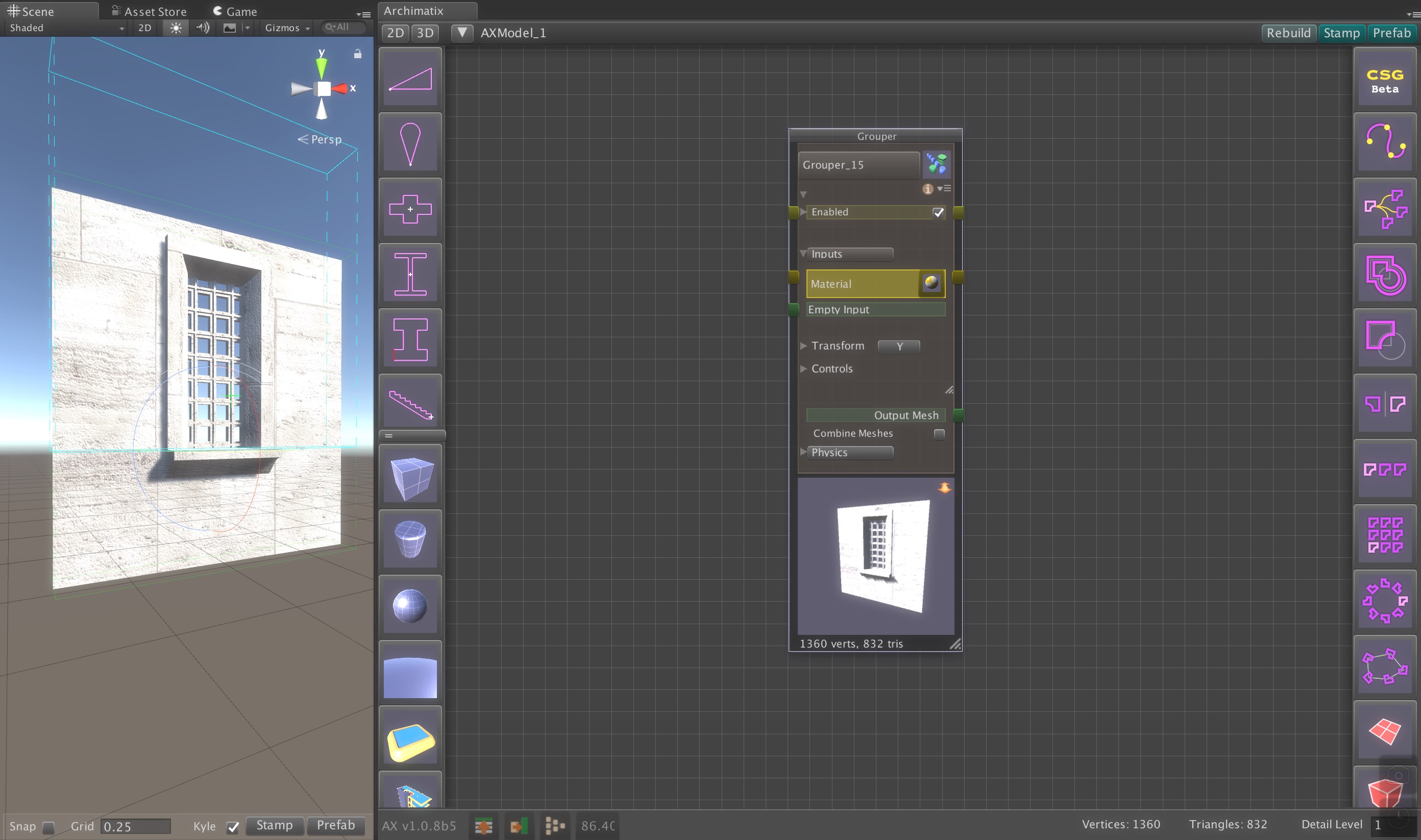
From the right sidebar menu, click on the Grouper Icon. In the new node palette that appears, click on the name of the Grouper and change its Name to GabledRoof.
Double click the thumbnail at the bottom of the Grouper node to open it.
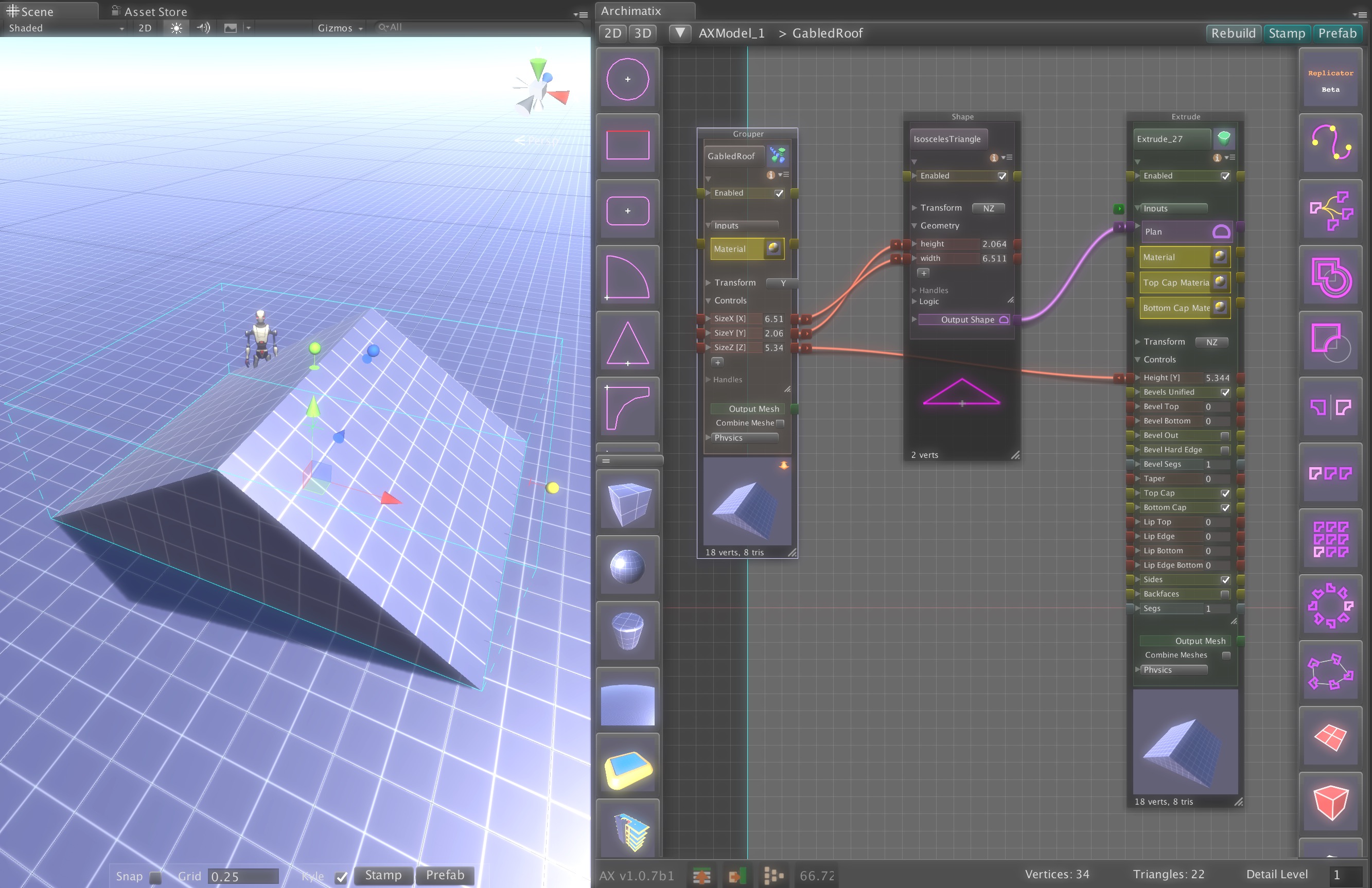
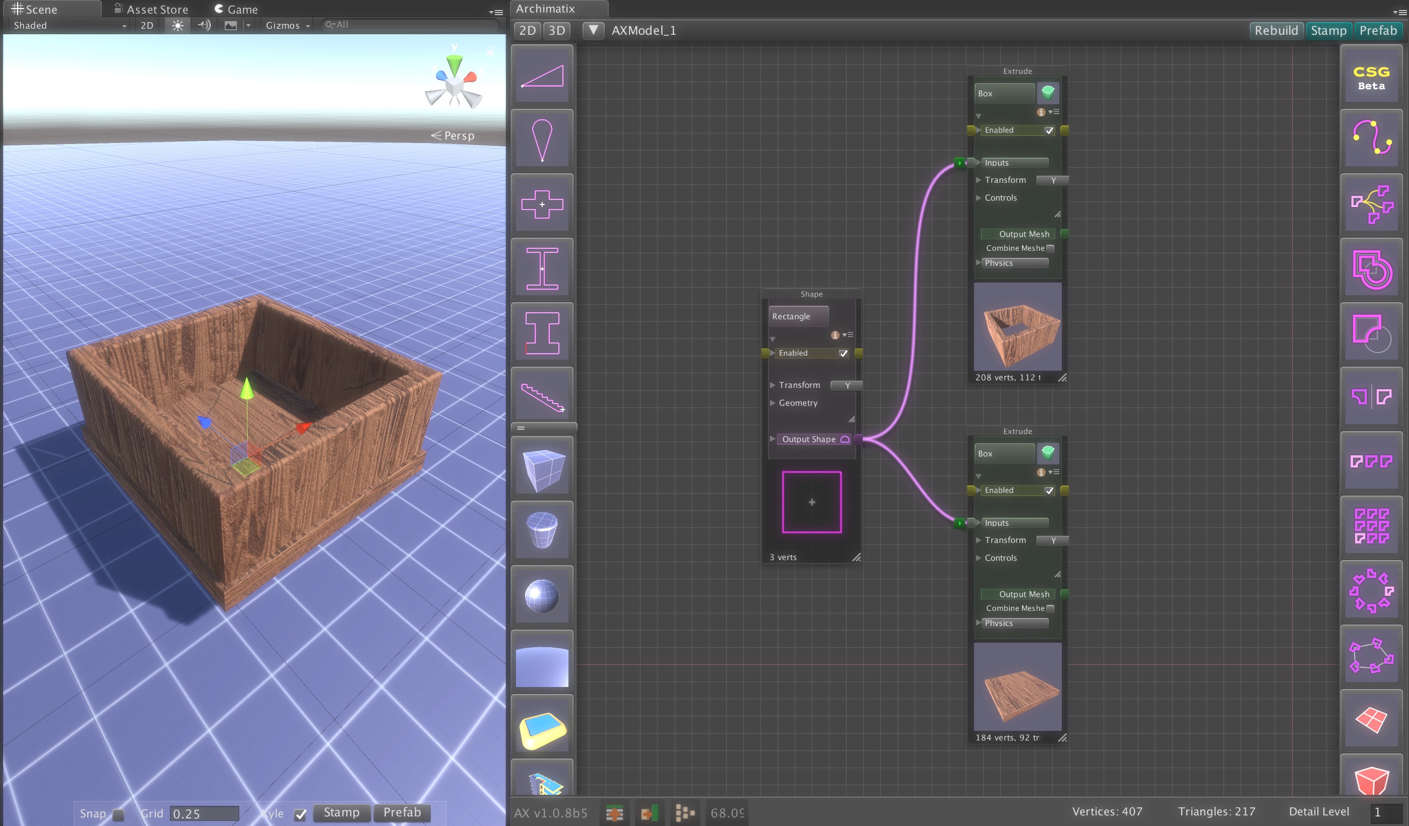
Step 2: Instantiate an Isosceles Triangle and Extrude it
When you click on the Isosceles Triangle in the left sidebar of the NodeGraph Editor, it will appear inside the Grouper. Click on its Output (2.1) and click on the Extrude node in the right sidebar. For Axis orientation in the Extrude node (2.2), choose negative-Z (NZ). Finally, open the Transforms foldout (2.3) and choose Centered for AlignZ.
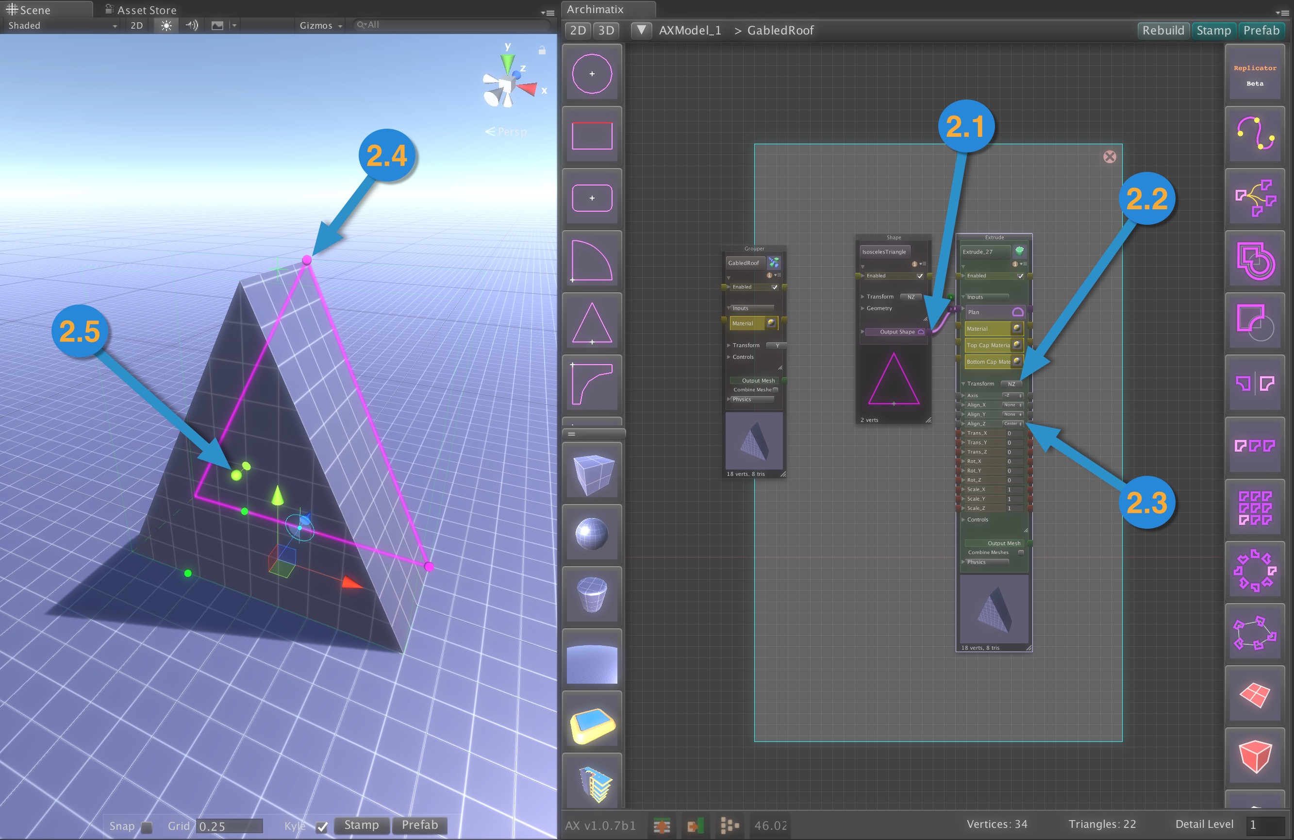
With the Extrude node selected, you should now be able to use the triangle’s point handles (2.4) and the extrude’s Z-axis handle (2.5) to control the form of the Gabled Roof’s form.
Well that was pretty easy, right? I’m glad you think so, since we are about to up the ante a bit…
Defining Richer Geometrical Relationships
While the building handles for the Triangle shape and the Extrude are already letting you choose just about any form you like, we might need more geometrical controllers and values. For example, what if we would like to control the pitch of the roof or use the diagonal length of the roof to make a rafter the right length?
A best practice in Archimatix is to let the Grouper provide a comprehensive interface for the parametric object. To start, lets relate the Grouper’s default bounding parameters to the Triangle and the Extrude nodes.
Step 3: Relate the Grouper’s default parameters to the Triangle and Extrude
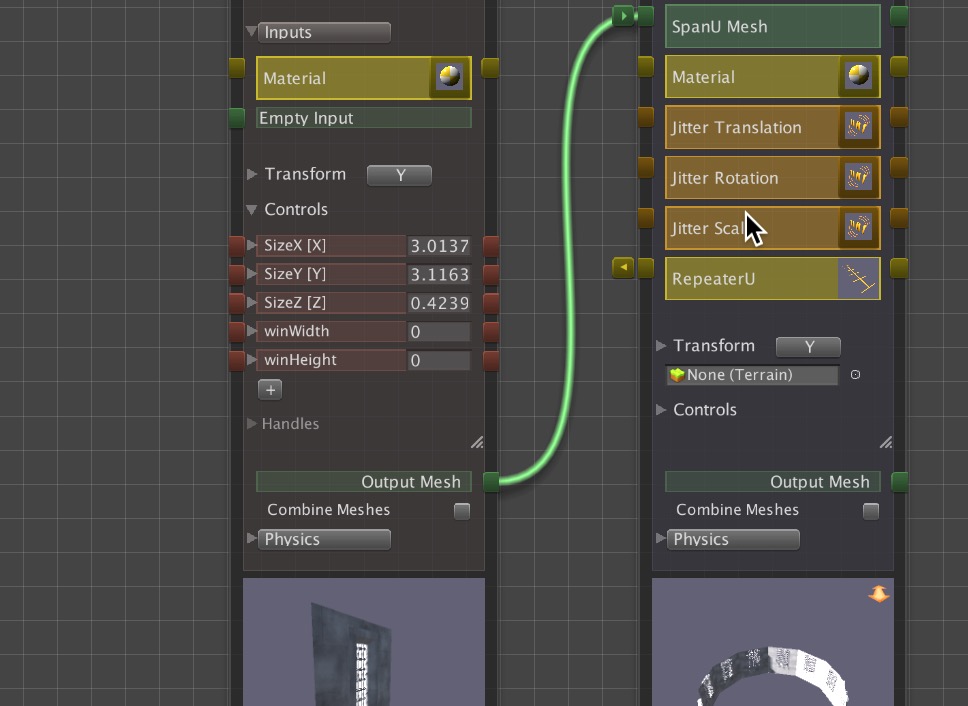
In the Node Graph Editor, make sure the Grouper is still open. Connect the Grouper’s SizeX to the Triangle Shape’s width parameter and the SizeY to the Shape Height. Connect the Grouper’s SizeZ to the Extrude’s Height parameter. Note that you can open the Controls foldouts after you have selected the Output of the Grouper’s Size parameters.
What has this relationship building done for us? For one, we can now close the Grouper (double-clicking on its thumbnail again) and control the form either the Grouper’s Controls sliders in the NodeGraph or its bounding handles in the Scene View.
Using the Grouper’s bounding handles to control the parametric object let’s us edit more as an object without worrying about the internal nodes of how it was constructed. As forms become more complex, the ability to abstract them using Grouper interface is key.
We can make this model richer still by adding more control parameters to the Grouper’s interface.
Step 4: Create New Grouper Parameters
In the Grouper, make sure the Controls foldout is open and click the “+” button to create a new Parameter. Name the Parameter pitchAngle. Add another parameter called rakingLength.
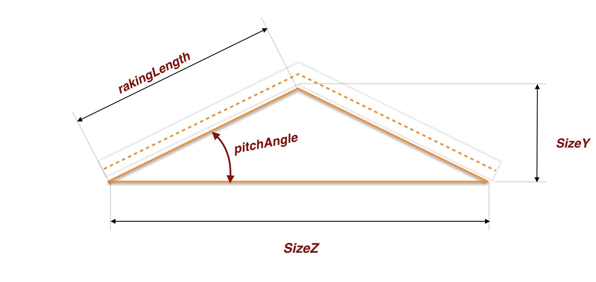
The pitchAngle my in some cases be a more desirable parameter to vary than SizeY. For example, you may want the pitch to be 45% and the the value of the height is not as important.
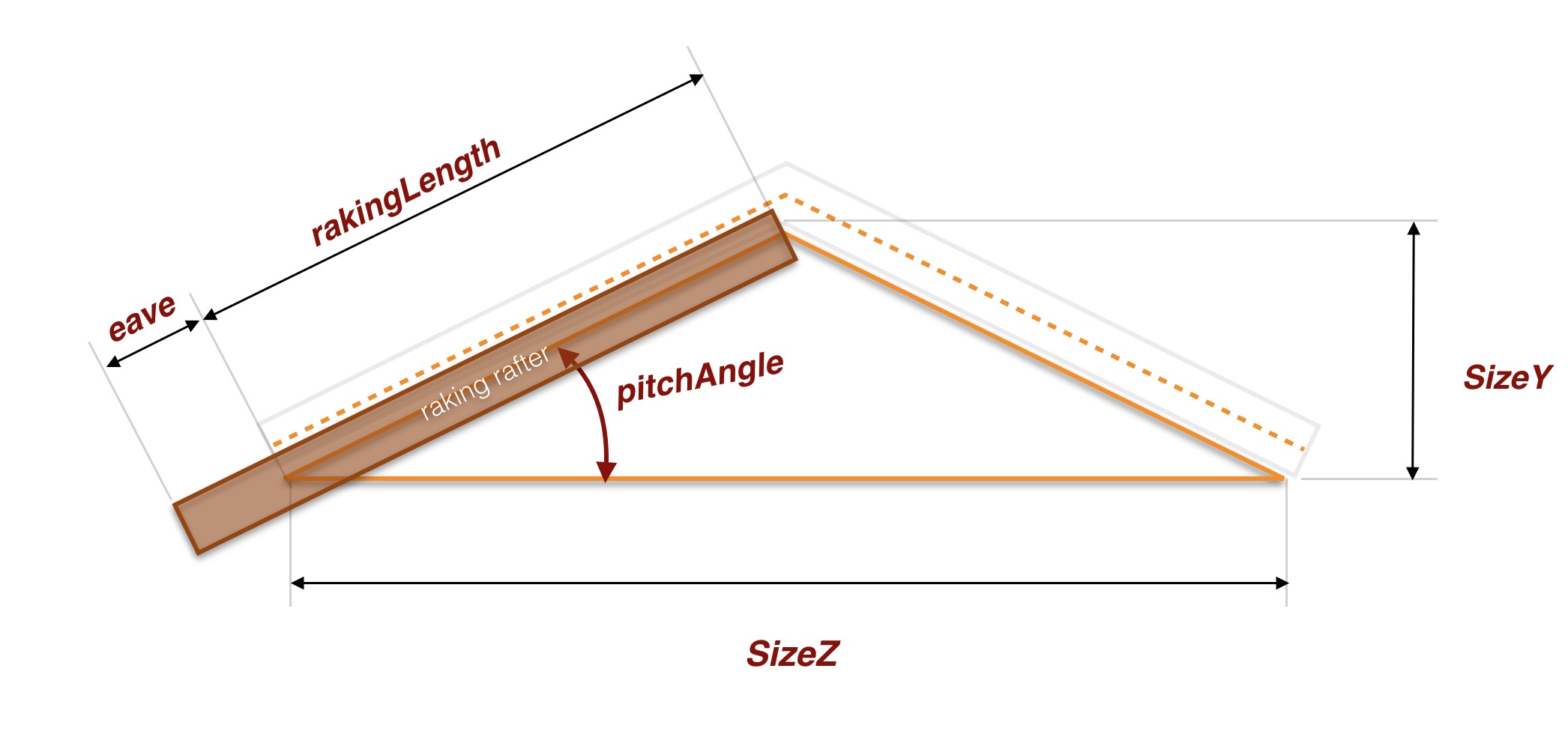
The rakingLength, which is the hypotenuse of the half triangle, is an important parameter to use in conjunction with the pitchAngle, if you want to add elements to the angled part of the roof, such as the raking rafters. To create a raking rafter, you can extrude a rectangle and relate the Height of the Extrude to the rakingLength and the relate its X-axis rotation, RotX to the pitchAngle. If you add another parameter to the Grouper called eave, you can extend the raking rafter so that it can
Step 5: Inter-relating Parameters with Expressions
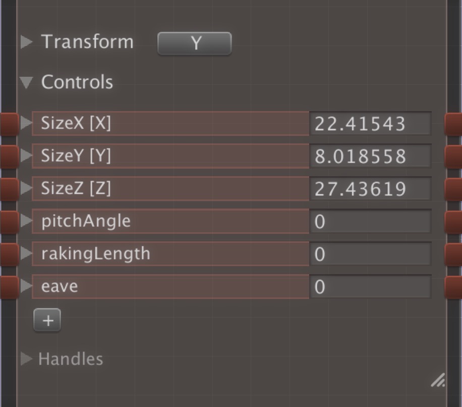 So far, you have added three custom parameters to the Grouper. At this point, your list of control parameters should look like the figure to the right.
These parameters are all inter-related geometrically, i.e., they are inter-dependent. For example, if the SizeY changes, either the pitchAngle must change OR the SizeZ must change. It is up to you, as the parametric designer, to decide the behavior of the model. You can decide what happens when the user of the model varies a particular parameter and encode this with the use of mathematical expressions.
Now, if you haven’t used your high school trigonometry in years, here’s your chance to dust it off and make real use of it! The pitchAngle is related to the SizeX and SizeY of the triangle with the expression:
pitchAngle = Atan2(SizeY, (SizeX/2))
Where Atan2 is the inverse tangent of Y over X. All of the Math functions have been mapped to Archimatix expression parsing so that you can simply call out the function name with out the Mathf. Now that we know the expression> where can we use it?
In terms of the model’s behavior, we may decide that when we alter the SizeY, the pitchAngle should recalculate itself so that it is always up to date. As it turns out, we can add this expression to the SizeY parameter.
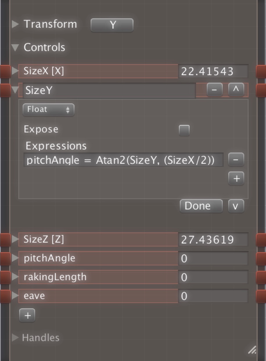 Open the foldout for the SizeY parameter and add the expression for pitch angle in the available Expressions field.
If you close the foldout and adjust the SizeY, you should see the pitchAngle changing to reflect the new geometry.
When the SizeY changes, the rakingLength is also affected. We should add another expression to reflect this geometrical constraint. The expression is:
rakingLength=SizeY/Sin(pitchAngle)
If you click the “+” button beneath the first expression, a new expression field will be added. Once you enter this expression and close the foldout, adjusting the SIzeY should now recalculate both the pitchAngle and the rakingLength. Since this Expression is comes after the first, the pitchAngle has already been calculated but the time the rakingLength is being processed.
These expressions will be executed only when the SizeY is changed. In other words, parameter expressions define what will happen when that parameter is changed. This means that the parameter, whose expression this is should be on the right side of the equation. In each expression, only one other parameter should be on the left side. The right side may include as many other parameters as you like within the same Grouper node. If there is some parameter on another node, whose value you would like to include in an expression, you can create a new parameter in the Grouper and relate it to the other node’s parameter.
What if we change the pitchAngle? Either the SizeZ needs to change OR the SizeY. As the parametric designers, we can choose either behavior. Let’s say that the SizeZ remains the same and the SizeY changes. To do define this behavior, let’s add an expression to the pitchAngle parameter. The expression should be:
SizeY=(SizeZ/2)*Tan(pitchAngle)
Once again, the rakingLength will also change, but we don’t need to specifically add the expression for this, since we are changing the SizeY and when the SizeY changes, it will execute its expression for the rakingLength.
Finally, we need to determine what happens when the SizeZ of the Gabled Roof is modified. Let’s leave the pitchAngle fixed and alter the SizeY. As it turns out, it is the same equation we added to the pitchAngle.
SizeY=(SizeZ/2)*Tan(pitchAngle)
As we can see, the decisions we make for how each parameter affects others is a design decision when the geometry we are describing has inter-dependent variables. It is up to us to create the behavior of the model based on our decisions of what should change when we are adhering to the constraints of the geometry.
Now that we have all these great parameters, let’s do something with them!
[To be continue…]

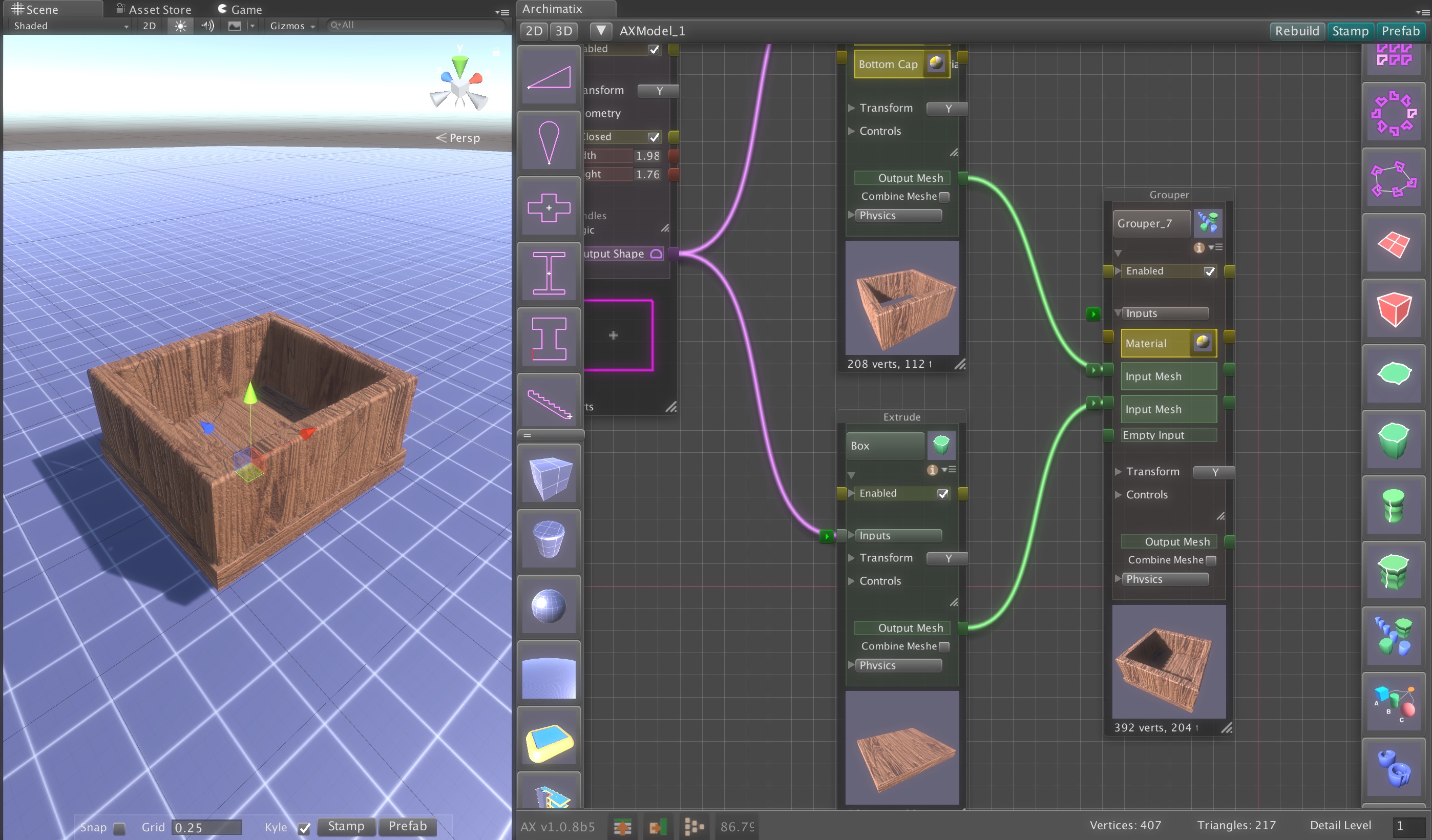

 For the wall lets use the default SizeX and SizeY of the Grouper.
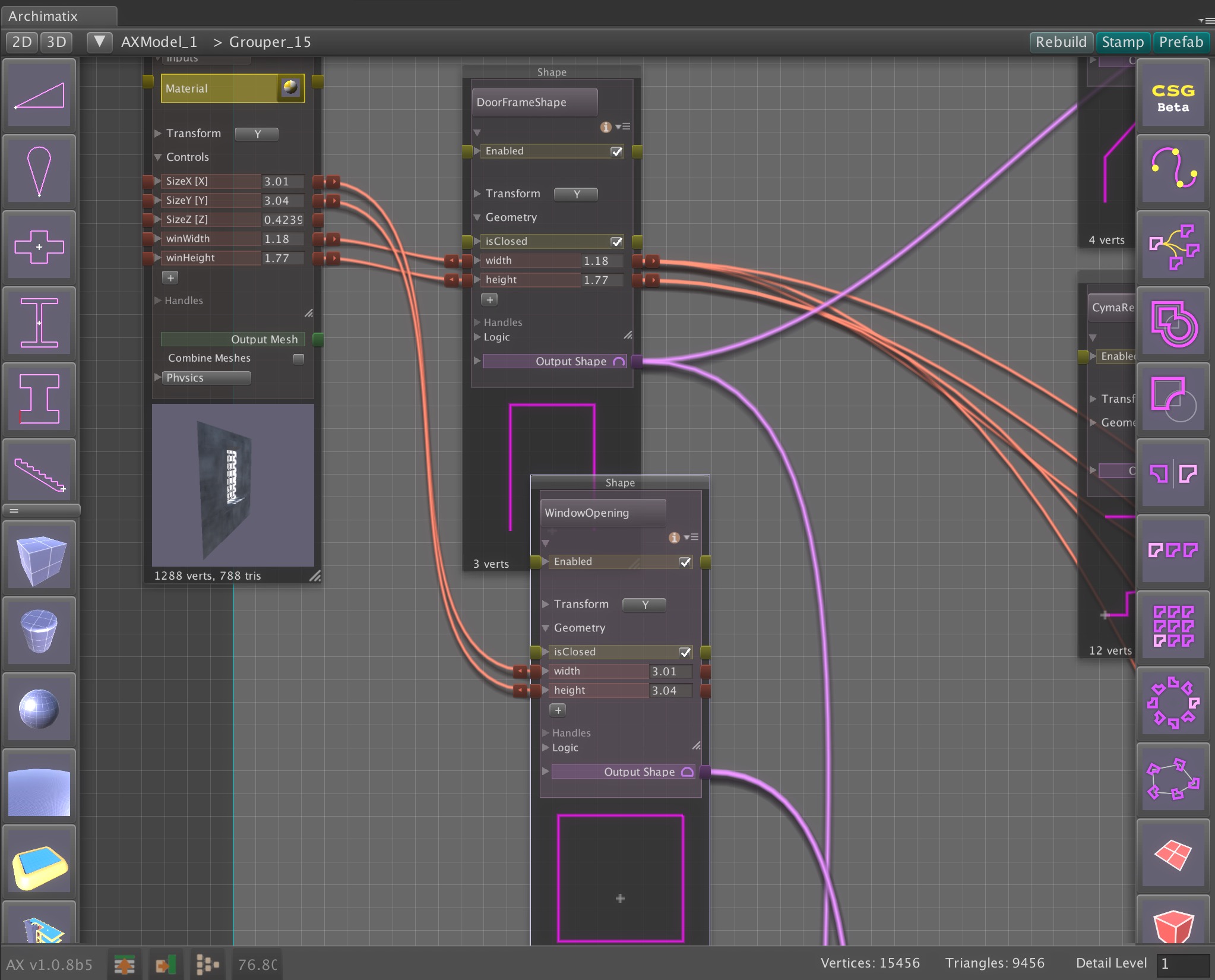


 If you don’t create your own node icon image, one will be automatically displayed for you in the right sidebar of the node graph. AS a generic icon, the only way a user will know that it creates an instance of your node is by the tool tip that appears when you mouse over it. For this reason, it is probably best to create your own distinctive look!
 In order to work contextually with the other nodes in the sidebar color-wise, you can use the blank image icon to the right as a background. Once your image is saved, select it in your Unity Project window and, in the Inspector, set the Texture Type to Editor GUI.
Recent Comments